Looking at
the device data sheet, I notice two things.
First, it's not a particularly high-speed device, even by '80s standards. It uses USB 2.0
full speed, 12 Mbps. I'm not convinced that a slightly suboptimal layout of it would cause serious problems. (I suspect that the document you were looking at about layout etc. may be more about USB 2.0
high speed, which at 480 Mbps is something where I'd imagine those kinds of layout techniques do make a noticable difference.)
hmm, i did read about that on
StackExchange, i still thought my design would be a problem because the traces are around 3cm long and go through a TH Resistor each.
Second, it looks as if it may not be implementing any of the standard device classes that would allow most OSes to immediately let you start using the device. The data sheet says, "FTDI’s royalty-free Virtual Com Port (VCP) and Direct (D2XX) drivers eliminate the requirement for USB driver development in most cases." Given that they supply their own drivers for "com port" and bulk data transfer, it would be reasonable that they wouldn't bother also to implement other standard protocols that are either less suitable (USB block storage device) or annoyingly slow (USB serial) for the application.
I did install the FTDI drivers before connecting it, it still gave the "device descriptor request failed" error message.
i assume if the chip wouldn't respond/work at all it just wouldn't show up in the device manager. (like any non data transfering USB device does)
Which is the reason I think that there is a problem on the PCB as even without drivers it should still show up as an unknown device (with Hardware ID and everything) without any errors.
I would carefully debug the existing board before ordering a new one. (It would be particularly frustrating to re-spin the board only to find the same problems!)
I checked all pins twice, with help of the datasheet, and all connections look and measured correctly (also no shorts between pins), I made sure the D+ and D- lines are correct and not switched around.
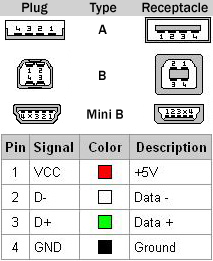
if this picture is accurate then i got the D- line connected to Pin 14 (USBDM) and D+ connected to Pin 13 (USBDP), which should be the right way around (acording to the datasheet)
- Untitldsaed.png (217.9 KiB) Viewed 1862 times
- If you're using Windows, make sure the correct drivers from FTDI are installed. Use any debugging tools they supply.
- You can plug the board into a Linux box and see what the kernel messages say about it. If it successfully attaches a generic device, you can use command line tools such as lsusb to get more details about exactly what it found, including device and endpoint descriptors.
- If Linux fails to attach even a generic device, try different cables and, if that fails, get a 'scope on to the D+ and D- lines (both ends!) to see what's going on there.
- Using either Linux or Windows, you can write small programs using libusb to poke at and probe the device to see how far you can get with communicating with it.
I know next to nothing about linux so i don't know how to do any of those things... and google isn't really helpful either sady...
i tried multiple cables, and currently i'm used the same cable i use for my TL866 II plus Programmer, so i know it's not the cable.
plus i sadly don't have an oscilloscope. i only got a simple logic probe (which is enough to tell that there is activity on both the D+ and D- bus)
the USBView program from FTDI shows strange stuff.
here is what my keyboard looks like in it:
and here what the FT240X looks like:
Obviously all of this is going to require some knowledge about how USB works. I have seen a great set of pages on this that could get someone at your level up to speed in no time flat, but I can't find the darn things now.

But
this article is short and might be fairly useful, and it also is probably worth at least scanning through the info on Wikipedia. I'll try to find better resources as we go along.
damn, the entire point of getting the chip was to avoid having to learn about the USB protocol.


