6502.org Forum  Projects  Code  Documents  Tools  Forum
It is currently Thu Sep 19, 2024 11:54 pm

All times are UTC


Post new topic Reply to topic  [ 24 posts ]  Go to page 1, 2  Next
Author Message
PostPosted: Sun Mar 24, 2019 8:23 pm 
Offline

Joined: Sun Mar 24, 2019 8:00 pm
Posts: 20
Greetings,

I am 19 years old and I have been interested in hardware for a long time, and for that reason I am now trying to learn more about digital electronics. I have a very strong interest in old computers(I even programmed a Pong clone in assembler for the C64), and for that reason I have decided that I wanted to make a 6502 computer.

As my first step, I decided I needed an EEPROM programmer. Since commercial ones are expensive I decided to make one with a couple of shift registers and an arduino.

After facing many difficulties with trying to write to a 28c256(and reading that it was very hard to disable the software write protection), I decided to first try to read and write to an HM62256(https://hardtofind.com.mx/pdfs/textos/H/HM62256A.PDF).

Even though this is supposed to be much simpler, I still was unable to write much of anything. After a few hours of debugging, I discovered that whatever input I gave to the OE pin, was mirrored in the A10 (If I gave a High signal to OE, A10 would output High, and if I gave OE a low signal, A10 would output low). At first I thought that the breadboard was perhaps shorted over these two rows, but when I removed the 62256, both signals were independent. I even tried a 28c256, and it also behaved normally.

I am also nearly 100% certain that I put the IC in the right orientation. This sram module does not have a notch at the top, but instead a small hole in the top left, which i understand should be at the top.

What could be causing this issue? Could the SRAM module be defective?

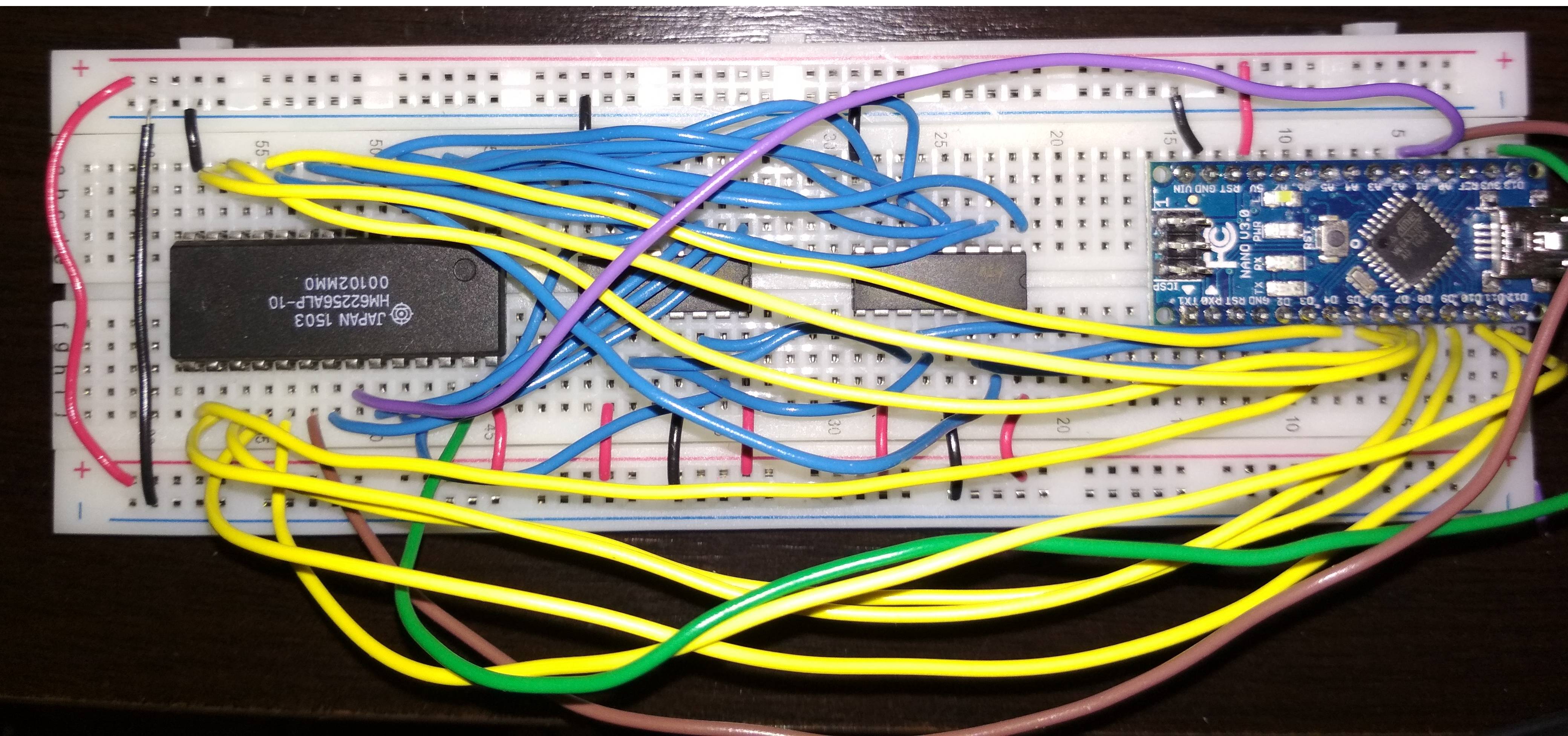
Here is a picture of my circuit, if it is of any help:
Image


Top
 Profile  
Reply with quote  
PostPosted: Sun Mar 24, 2019 8:30 pm 
Offline
User avatar

Joined: Thu Dec 11, 2008 1:28 pm
Posts: 10938
Location: England
Welcome! Always good to see a new enthusiast.

If your chip came from a reputable supplier, or has been seen working at least once, then your circuit is most likely to be the issue. But if your chip might possibly be some other chip relabelled by an unscrupulous supplier, that could be it.

There's no substitute for slowly and methodically checking everything: your design, the pinouts, the wiring.


Top
 Profile  
Reply with quote  
PostPosted: Sun Mar 24, 2019 8:50 pm 
Offline

Joined: Sun Mar 24, 2019 8:00 pm
Posts: 20
BigEd wrote:
Welcome! Always good to see a new enthusiast.

If your chip came from a reputable supplier, or has been seen working at least once, then your circuit is most likely to be the issue. But if your chip might possibly be some other chip relabelled by an unscrupulous supplier, that could be it.

There's no substitute for slowly and methodically checking everything: your design, the pinouts, the wiring.


Hello BigEd, thank you for your reply.

Like I said, I've spent many hours debugging and testing everything, and I believe I have narrowed down the problem as far as I can:

If I set the wire to OE to high, the A10 pin on the 62256 will be set to high as well, regardless of what the shift register is outputting to that position. Likewise, if I set OE to low, the A10 pin on the 62256 will output low. As far as I can tell, the address pins are only ever supposed to take input, and never generate an output, so this strikes me as extremely odd.

I'm fairly certain it is not a byproduct of my programming or perhaps a defect in the breadboard, since I have tested it both with an at28c256 as well as with no IC in that position at all, and those positions behave normally, with the A10 position being completely independent from OE. Thus, I can only conclude that the connection between OE and A10 must exist within the HM62256 IC.

The store I bought it from is a pretty large and established one here in my country, so I can't imagine they would sell me a fake. However, this Hitachi chip was about half the price of a similar Samsung one, so perhaps it could be the problem.

How could it happen that A10 could be outputting the input of the OE pin, even if A10 is only ever supposed to take input?


Top
 Profile  
Reply with quote  
PostPosted: Sun Mar 24, 2019 9:06 pm 
Offline
User avatar

Joined: Fri Aug 30, 2002 1:09 am
Posts: 8509
Location: Southern California
Those are pins 21 and 22, ie, right next to each other. If you look under the IC, do you see any solder splashes or anything else that could short them together? With the IC not in the circuit, does a DMM confirm they're shorted? If there were internal static damage, I suspect a pin would be shorted to VDD or ground, not a neighboring signal pin. There seems to be a growing problem of counterfeit, mislabeled ICs coming out of China, where shops pull ICs out of boards that are either used or for some reason did not pass production test, and they clean them up, sand the labels off and they print new labels on them to make them appear like they're something they're not, in order to make them more attractive.

_________________
http://WilsonMinesCo.com/ lots of 6502 resources
The "second front page" is http://wilsonminesco.com/links.html .
What's an additional VIA among friends, anyhow?


Top
 Profile  
Reply with quote  
PostPosted: Sun Mar 24, 2019 9:46 pm 
Offline
User avatar

Joined: Fri Dec 11, 2009 3:50 pm
Posts: 3367
Location: Ontario, Canada
Welcome, Solater! :)

Can you tell us more about how you are using the shift registers? I assume they supply the address bits to the RAM, is that correct? Do they also supply the OE signal?

Also: although I doubt this directly affects the problem, your power supply wiring is poor, and could be improved (see image). I suggest you add extra conductors as shown to connect the upper and lower power rails together. Yes, they are already connected at the far left, but for IC's connecting to the bottom rails the path back to the Arduno is quite long, and wiring for digital circuits is best kept short. It's OK to have redundant power and ground connections. I notice the Arduino has a ground pin along the lower edge, so I tapped into that, too! :) Also you have no bypass capacitors installed. I've marked one of many possible capacitor locations.

Please answer regarding the shift registers. Better yet, can you provide a schematic?

cheers
Jeff
Attachment:
pOCwSBz_ann.jpg
pOCwSBz_ann.jpg [ 231.11 KiB | Viewed 1893 times ]

_________________
In 1988 my 65C02 got six new registers and 44 new full-speed instructions!
https://laughtonelectronics.com/Arcana/ ... mmary.html


Top
 Profile  
Reply with quote  
PostPosted: Sun Mar 24, 2019 10:35 pm 
Offline

Joined: Sun Mar 24, 2019 8:00 pm
Posts: 20
GARTHWILSON wrote:
Those are pins 21 and 22, ie, right next to each other. If you look under the IC, do you see any solder splashes or anything else that could short them together? With the IC not in the circuit, does a DMM confirm they're shorted? If there were internal static damage, I suspect a pin would be shorted to VDD or ground, not a neighboring signal pin. There seems to be a growing problem of counterfeit, mislabeled ICs coming out of China, where shops pull ICs out of boards that are either used or for some reason did not pass production test, and they clean them up, sand the labels off and they print new labels on them to make them appear like they're something they're not, in order to make them more attractive.


Hello Garth, thank you for your response.

I've tested the resistance of the pins with a multimeter and I do get a reading, so it looks as though they are directly connected. I have also examined the IC, and I can't see any solder splashes. However, I can see a small metallic spot on the side exactly in between the two offending pins.

Do you think that this is a counterfeit? I could probably go to the store and complain.

This is a picture of the metallic spot I talk about for reference:
Image


Top
 Profile  
Reply with quote  
PostPosted: Sun Mar 24, 2019 10:48 pm 
Offline

Joined: Sun Mar 24, 2019 8:00 pm
Posts: 20
Dr Jefyll wrote:
Welcome, Solater! :)

Can you tell us more about how you are using the shift registers? I assume they supply the address bits to the RAM, is that correct? Do they also supply the OE signal?

Also: although I doubt this directly affects the problem, your power supply wiring is poor, and could be improved (see image). I suggest you add extra conductors as shown to connect the upper and lower power rails together. Yes, they are already connected at the far left, but for IC's connecting to the bottom rails the path back to the Arduno is quite long, and wiring for digital circuits is best kept short. It's OK to have redundant power and ground connections. I notice the Arduino has a ground pin along the lower edge, so I tapped into that, too! :) Also you have no bypass capacitors installed. I've marked one of many possible capacitor locations.

Please answer regarding the shift registers. Better yet, can you provide a schematic?

cheers
Jeff
Attachment:
pOCwSBz_ann.jpg


Hello Jeff,

The shift registers only supply the 15 address bits, so that the last bit of the second register is unused. The OE signal comes from the A1 port on the arduino (the purple wire on the image).

Thanks for the advice! I will modify my circuit as you recommend. At one point i did have a bypass capacitor across the 62256 IC's ground and 5v. Do you think that is of any use, or should I just put my capacitor(s) on the power rails, given that I am using a breadboard?

My schematic is very similar to this one, the only difference being that I have direct lines to the arduino for the CE and OE signals:
https://github.com/beneater/eeprom-programmer

I didn't use the same code however, I wrote my own to stick as closely to the timings in the datasheet as possible (or as well as I could understand the timing diagrams).


Top
 Profile  
Reply with quote  
PostPosted: Mon Mar 25, 2019 2:08 am 
Offline
User avatar

Joined: Fri Dec 11, 2009 3:50 pm
Posts: 3367
Location: Ontario, Canada
I could be wrong, but I'd say the metallic spot has no significance. I suspect it results from the way the lead frame of the chip is manufactured, and is normal. But of course the chip still could be counterfeit, or damaged perhaps.

Solater wrote:
I've tested the resistance of the pins with a multimeter and I do get a reading, so it looks as though they are directly connected.
Just as a sanity check, how does the reading from OE to A10 compare with the reading from OE to A11, say, or OE to any other address input? Can we say that the reading from OE to A10 is conspicuously different?

Quote:
At one point i did have a bypass capacitor across the 62256 IC's ground and 5v. Do you think that is of any use, or should I just put my capacitor(s) on the power rails
Probably it's most effective if the cap goes directly from ground to 5v -- diagonally across the chip, I mean. If you're careful you can solder the cap directly to the chip, and that's what will result in the shortest connections. But you could put a cap(s) on the rails instead, or as well. TBH, it's hard to know what will be "good enough." Some situations are quite forgiving; others are more critical. Caps are cheap, and fairly easy to put in, so it's silly not to have at least a few. One for each chip is nice.

_________________
In 1988 my 65C02 got six new registers and 44 new full-speed instructions!
https://laughtonelectronics.com/Arcana/ ... mmary.html


Top
 Profile  
Reply with quote  
PostPosted: Mon Mar 25, 2019 2:29 am 
Offline

Joined: Sun Mar 24, 2019 8:00 pm
Posts: 20
Dr Jefyll wrote:
Solater wrote:
I've tested the resistance of the pins with a multimeter and I do get a reading, so it looks as though they are directly connected.
Just as a sanity check, how does the reading from OE to A10 compare with the reading from OE to A11, say, or OE to any other address input? Can we say that the reading from OE to A10 is conspicuously different?

I've tested quite a few other pin combinations (though not all of them), and I don't get a reading at all, not even with 5v to ground. With A10 to OE, I get around 1.4 ohms.

Dr Jefyll wrote:
Quote:
At one point i did have a bypass capacitor across the 62256 IC's ground and 5v. Do you think that is of any use, or should I just put my capacitor(s) on the power rails
Probably it's most effective if the cap goes directly from ground to 5v -- diagonally across the chip, I mean. If you're careful you can solder the cap directly to the chip, and that's what will result in the shortest connections. But you could put a cap(s) on the rails instead, or as well. TBH, it's hard to know what will be "good enough." Some situations are quite forgiving; others are more critical. Caps are cheap, and fairly easy to put in, so it's silly not to have at least a few. One for each chip is nice.

Is it okay to solder directly onto the legs of the IC? Won't the heat damage it?


Top
 Profile  
Reply with quote  
PostPosted: Mon Mar 25, 2019 2:46 am 
Offline
User avatar

Joined: Fri Dec 11, 2009 3:50 pm
Posts: 3367
Location: Ontario, Canada
Solater wrote:
Won't the heat damage [ the IC ]?
No, not unless you take a LONG time to do the soldering. A fine tip on the iron is helpful. And you want it to be fairly hot so the job can be done quickly. If you have any extra/worthless IC's around you can practice soldering on them.

Edit: I found a photo.
Attachment:
0937RotCrop1Lores .jpg
0937RotCrop1Lores .jpg [ 29.8 KiB | Viewed 1870 times ]

Edit 2: And here's a better photo. The leads have less unnecessary length (and this is assisted by the choice of axial-lead rather than radial-lead caps). In addition to the soldered version on the left, on the right we see an alternative arrangement intended specifically for wireless breadboard. It's easier, of course, though not quite as good as direct attachment to the chip.
Attachment:
bypass capacitors.JPG
bypass capacitors.JPG [ 276.71 KiB | Viewed 1825 times ]


Solater wrote:
With A10 to OE, I get around 1.4 ohms.
Well, we don't know how it got that way, but that's certainly not right.

If you feel like fooling around, you might be able to permanently ground those pins and still test the circuit using only 16K of the 32K RAM. This will be a little tricky, but by observing the Truth Table for the RAM you could modify your program so that OE can be permanently low. But only if that seems like a fun challenge for you! And it might not work anyway if the chip is utterly dead -- or not even a RAM at all. If so, it's time to find a new chip. :|

-- Jeff

_________________
In 1988 my 65C02 got six new registers and 44 new full-speed instructions!
https://laughtonelectronics.com/Arcana/ ... mmary.html


Last edited by Dr Jefyll on Mon Mar 25, 2019 7:28 pm, edited 2 times in total.

Top
 Profile  
Reply with quote  
PostPosted: Mon Mar 25, 2019 3:04 am 
Offline

Joined: Sun Mar 24, 2019 8:00 pm
Posts: 20
Dr Jefyll wrote:
Solater wrote:
Won't the heat damage it?
No, not unless you take a LONG time to do the soldering. A fine tip on the iron is helpful. And you want it to be fairly hot so the job can be done quickly. If you have any extra/worthless IC's around you can practice soldering on them.

Solater wrote:
With A10 to OE, I get around 1.4 ohms.
Well, we don't know how it got that way, but that's certainly not right.

If you feel like fooling around, you might be able to permanently ground those pins and still test the circuit using only 16K of the 32K RAM. This will be a little tricky, but by observing the Truth Table for the RAM you could modify your program so that OE can be permanently low. But only if that seems like a fun challenge for you! And it might not work anyway if the chip is utterly dead. If so, it's time to find a new RAM chip. :|


I just went ahead and tied the OE and A10 pins to low, and now it works perfectly well! Looks like the chip isn't completely fake, it's just defective. I'll go ahead and let the people at my local electronics store know, and I'll get a new one afterwards.

Thanks a lot for your help!


Top
 Profile  
Reply with quote  
PostPosted: Mon Mar 25, 2019 3:26 am 
Offline
User avatar

Joined: Fri Dec 11, 2009 3:50 pm
Posts: 3367
Location: Ontario, Canada
You're welcome! :) But of course we know that, with one of the address lines out of service, the chip can only store 16K bytes. When you try to read back, what you get is two copies of the same 16K. Perhaps the program you're using fails to perceive the error.

As for the 28c256, for a brand new chip it seems to me that any write protection would be disabled when the chip leaves the factory. Or was your chip used/surplus? In any case, I suggest you get a 2nd opinion about write protection.

-- Jeff

_________________
In 1988 my 65C02 got six new registers and 44 new full-speed instructions!
https://laughtonelectronics.com/Arcana/ ... mmary.html


Top
 Profile  
Reply with quote  
PostPosted: Mon Mar 25, 2019 3:50 am 
Offline

Joined: Sun Mar 24, 2019 8:00 pm
Posts: 20
Dr Jefyll wrote:
As for the 28c256, for a brand new chip it seems to me that any write protection would be disabled when the chip leaves the factory. Or was your chip used/surplus? In any case, I suggest you get a 2nd opinion about write protection.

The 28c256 is supposed to be brand new, it came from the same store as the SRAM. It does say on the datasheet that it should have software protection disabled by default, but I've read online that many of the new chips have it enabled from the factory regardless. I tried writing to my own 28c256, and I was unsuccessful, as the data on the chip never changed, no matter what I did, and this has led me to believe that my chip has SDP enabled.

I haven't found out about anyone who has been able to disable the software protection successfully (Without using an official programmer). I don't want to buy a programmer, so I think I will just attach a battery to an SRAM chip instead. I've heard that's how some people did it in the old days anyways.


Top
 Profile  
Reply with quote  
PostPosted: Mon Mar 25, 2019 4:55 am 
Offline
User avatar

Joined: Fri Dec 11, 2009 3:50 pm
Posts: 3367
Location: Ontario, Canada
Solater wrote:
it came from the same store as the SRAM
Uhhhh... :roll: :P

_________________
In 1988 my 65C02 got six new registers and 44 new full-speed instructions!
https://laughtonelectronics.com/Arcana/ ... mmary.html


Top
 Profile  
Reply with quote  
PostPosted: Mon Mar 25, 2019 5:12 am 
Offline

Joined: Sat Jun 04, 2016 10:22 pm
Posts: 483
Location: Australia
If the EEPROM you're talking about is an Atmel/Microchip AT28C256, I've successfully disabled the software write protection before, and written to it in-circuit, but that was using an already-working 65C02 system.
I haven't made much use of that fact yet, but I have done so.

Disabling the software write protection is a matter of writing the correct sequence of writes to the device. The addresses and data required should be in the datasheet.


Top
 Profile  
Reply with quote  
Display posts from previous:  Sort by  
Post new topic Reply to topic  [ 24 posts ]  Go to page 1, 2  Next

All times are UTC


Who is online

Users browsing this forum: No registered users and 26 guests


You cannot post new topics in this forum
You cannot reply to topics in this forum
You cannot edit your posts in this forum
You cannot delete your posts in this forum
You cannot post attachments in this forum

Search for:
Jump to: