65XX SBC general help and color display help needed
-
GARTHWILSON

- Forum Moderator
- Posts: 8775
- Joined: 30 Aug 2002
- Location: Southern California
- Contact:
Re: 65XX SBC general help and color display help needed
That's where the MC145406 (same thing as the SN75C1406) triple line driver and receiver is nice if you already have ±12V for other things on the board, because you won't need any of those capacitors, since it doesn't need the charge pump.
http://WilsonMinesCo.com/ lots of 6502 resources
The "second front page" is http://wilsonminesco.com/links.html .
What's an additional VIA among friends, anyhow?
The "second front page" is http://wilsonminesco.com/links.html .
What's an additional VIA among friends, anyhow?

Re: 65XX SBC general help and color display help needed
Or... you could eliminate the transceiver IC and just have a header with the TTL level signals. Then simply plug in a USB-to-TTL Serial adapter or an RS232-to-TTL Serial adapter...
I still have a bag full of little circuit boards that fit inside a DB9 connector & hood for the RS232-to-TTL adapter shown below...
Cheerful regards, Mike
I still have a bag full of little circuit boards that fit inside a DB9 connector & hood for the RS232-to-TTL adapter shown below...
Cheerful regards, Mike
- Attachments
-
-
GARTHWILSON
- Forum Moderator
- Posts: 8775
- Joined: 30 Aug 2002
- Location: Southern California
- Contact:
Re: 65XX SBC general help and color display help needed
A nice thing about the line drivers and receivers is having everything in the office compatible, that is, everything that is, or pretends to be, RS-232, plus the protection against static discharge, and the assurance that you're not going to harm anything if a line gets shorted or something like that. The line drivers and receivers are kind of bullet-proof. There were hand-held terminals years ago that connected by RS-232 (although usually from smaller plugs, like RJ-45, IIRC) and the hand-held unit ran off of power scavenged off the RS-232 lines so it didn't need its own batteries. I definitely like the hardware handshaking of at least RTS & CTS. I use DTR and DSR too, but I could go without those.
http://WilsonMinesCo.com/ lots of 6502 resources
The "second front page" is http://wilsonminesco.com/links.html .
What's an additional VIA among friends, anyhow?
The "second front page" is http://wilsonminesco.com/links.html .
What's an additional VIA among friends, anyhow?
-
backspace119
- Posts: 346
- Joined: 25 Jan 2019
- Location: Knoxville, TN
Re: 65XX SBC general help and color display help needed
Michael wrote:
backspace119 wrote:
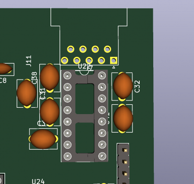
In other news, I sourced new 1uf caps that are non polarized, but I'm probably going to switch back, because the footprints are actually larger:
In other news, I've been considering a monostable circuit for driving RDY low when talking to the EEPROM. My plan is to drop it for 150ns, which should be enough time for most EEPROMs (a couple take 200, but I'll stay away from those). I found this AHC series IC that seems to be right for the job. If my math is right, I'll need a 10pf cap, and a 3.3kOhm resistor to achieve 150ns. (I originally was planning >1000pf cap to keep it simple with a k factor of 1, but there's a note in there stating to be careful with large value caps, as they can damage the chip if the power supply cuts off too quickly, so instead I went for the smallest cap possible, and a k factor of 4.5)
-
backspace119
- Posts: 346
- Joined: 25 Jan 2019
- Location: Knoxville, TN
Re: 65XX SBC general help and color display help needed
Michael wrote:
Or... you could eliminate the transceiver IC and just have a header with the TTL level signals. Then simply plug in a USB-to-TTL Serial adapter or an RS232-to-TTL Serial adapter...
I still have a bag full of little circuit boards that fit inside a DB9 connector & hood for the RS232-to-TTL adapter shown below...
Cheerful regards, Mike
I still have a bag full of little circuit boards that fit inside a DB9 connector & hood for the RS232-to-TTL adapter shown below...
Cheerful regards, Mike

Re: 65XX SBC general help and color display help needed
I always use TTL level for my UARTs, using 3 pin Molex
-
backspace119
- Posts: 346
- Joined: 25 Jan 2019
- Location: Knoxville, TN
Re: 65XX SBC general help and color display help needed
GARTHWILSON wrote:
That's where the MC145406 triple line driver and receiver is nice if you already have ±12V for other things on the board, because you won't need any of those capacitors, since it doesn't need the charge pump.
Something I asked a while ago and just remembered it never got answered, I have the CTS and RTS connected for the USB-TTL header, through resistors like the Rx and Tx lines, my assumption was this would give me hardware handshaking on it, but I seem to remember that...Daryl's? page didn't use those lines for the usb-ttl header.
Can I use these lines? Will they provide hardware handshaking?
-
backspace119
- Posts: 346
- Joined: 25 Jan 2019
- Location: Knoxville, TN
Re: 65XX SBC general help and color display help needed
Something I just realized is, if I use a monostable circuit for RDY generation, I can use a variable clock and be fine, since the clock won't be changing to access the EEPROM
does this sound feasible?
does this sound feasible?
Re: 65XX SBC general help and color display help needed
RDY needs to be synchronized to clock, though
-
backspace119
- Posts: 346
- Joined: 25 Jan 2019
- Location: Knoxville, TN
Re: 65XX SBC general help and color display help needed
Arlet wrote:
RDY needs to be synchronized to clock, though
Re: 65XX SBC general help and color display help needed
Signals like RDY go inside the CPU and are then distributed to dozens of different flip-flops, all switching on the same clock.
If RDY is allowed to change at any time, then it could change at the same as the clock, and some flip-flops would then see it as '0' and others as '1' due to small variance in timing and thresholds.
If RDY is allowed to change at any time, then it could change at the same as the clock, and some flip-flops would then see it as '0' and others as '1' due to small variance in timing and thresholds.
-
backspace119
- Posts: 346
- Joined: 25 Jan 2019
- Location: Knoxville, TN
Re: 65XX SBC general help and color display help needed
Arlet wrote:
Signals like RDY go inside the CPU and are then distributed to dozens of different flip-flops, all switching on the same clock.
If RDY is allowed to change at any time, then it could change at the same as the clock, and some flip-flops would then see it as '0' and others as '1' due to small variance in timing and thresholds.
If RDY is allowed to change at any time, then it could change at the same as the clock, and some flip-flops would then see it as '0' and others as '1' due to small variance in timing and thresholds.
The name of the game here is saving wait states, because I don't think 2 is adequate at 20Mhz operation for 150ns eeprom, and I'd like to use only a single dual flipflop chip.
I may look at some NVRAM that has 70ns access time
Re: 65XX SBC general help and color display help needed
You could use asynchronous delay and then feed it through flip-flop to synchronize it.
-
backspace119
- Posts: 346
- Joined: 25 Jan 2019
- Location: Knoxville, TN
Re: 65XX SBC general help and color display help needed
Arlet wrote:
You could use asynchronous delay and then feed it through flip-flop to synchronize it.
-
GARTHWILSON
- Forum Moderator
- Posts: 8775
- Joined: 30 Aug 2002
- Location: Southern California
- Contact:
Re: 65XX SBC general help and color display help needed
backspace119 wrote:
GARTHWILSON wrote:
That's where the MC145406 triple line driver and receiver is nice if you already have ±12V for other things on the board, because you won't need any of those capacitors, since it doesn't need the charge pump.
Quote:
Something I asked a while ago and just remembered it never got answered, I have the CTS and RTS connected for the USB-TTL header, through resistors like the Rx and Tx lines, my assumption was this would give me hardware handshaking on it, but I seem to remember that...Daryl's? page didn't use those lines for the usb-ttl header.
Can I use these lines? Will they provide hardware handshaking?
Can I use these lines? Will they provide hardware handshaking?
http://WilsonMinesCo.com/ lots of 6502 resources
The "second front page" is http://wilsonminesco.com/links.html .
What's an additional VIA among friends, anyhow?
The "second front page" is http://wilsonminesco.com/links.html .
What's an additional VIA among friends, anyhow?