6502.org Forum  Projects  Code  Documents  Tools  Forum
It is currently Thu Nov 14, 2024 10:03 pm

All times are UTC


Post new topic Reply to topic  [ 128 posts ]  Go to page Previous  1 ... 4, 5, 6, 7, 8, 9  Next
Author Message
PostPosted: Wed Jan 30, 2019 6:43 pm 
Online
User avatar

Joined: Fri Aug 30, 2002 1:09 am
Posts: 8540
Location: Southern California
hitlp wrote:
What would be the maximum acceptable time of edge rate?

That depends on the construction. Parts that are rated for 1 or 2MHz also tend to have slow edge rates that let you get away with murder, ie, solderless breadboards. But then you drop in a faster part, even running it at the same clock speed, and things quit working. If we can get a good picture, we can probably suggest, via photo editing, some changes in connection methods that will get things going again.

_________________
http://WilsonMinesCo.com/ lots of 6502 resources
The "second front page" is http://wilsonminesco.com/links.html .
What's an additional VIA among friends, anyhow?


Top
 Profile  
Reply with quote  
PostPosted: Thu Jan 31, 2019 11:24 am 
Offline

Joined: Sun Apr 10, 2011 8:29 am
Posts: 597
Location: Norway/Japan
Martin A wrote:
The 4 that I was given, that all tested as re-marked NMOS parts, have the following on them:
UMC
W65C02S8P-10
0119S

In other words, this ebay store (huayi-components) is selling fakes. Don't go there.


Top
 Profile  
Reply with quote  
PostPosted: Wed Feb 13, 2019 2:44 am 
Offline

Joined: Wed Dec 05, 2018 7:52 pm
Posts: 48
Hello guys.

It's me again and I'm just totally stuck. I reset all my circuit and simply when I set up the data bus to run NOP forever, A0 stays at 500 Hz. That is, it is not consuming 2 CPU cycles. Is it possible for this processor to have a "cache" of execution?

If you can also put a link where I can buy an original 6502, I thank you immensely.

Below are images.


Attachments:
osciloscope_01.PNG
osciloscope_01.PNG [ 14.05 KiB | Viewed 1001 times ]
20190213_003752.jpg
20190213_003752.jpg [ 6.22 MiB | Viewed 1001 times ]
Top
 Profile  
Reply with quote  
PostPosted: Wed Feb 13, 2019 3:09 am 
Offline

Joined: Mon May 21, 2018 8:09 pm
Posts: 1462
Wow, that looks like a *really* faded Rockwell logo, and there's no other markings visible in the photo.

Here's one relatively reputable option. They don't guarantee what brand of 6502 you'll get, and I'm not sure they would 100% test everything they get, but they at least won't *deliberately* rip you off.

Or you could order a brand-new WDC part from Mouser, who are an Authorised Distributor.


Top
 Profile  
Reply with quote  
PostPosted: Wed Feb 13, 2019 4:06 am 
Offline

Joined: Sat Dec 13, 2003 3:37 pm
Posts: 1004
hitlp wrote:
Hello guys.

It's me again and I'm just totally stuck. I reset all my circuit and simply when I set up the data bus to run NOP forever, A0 stays at 500 Hz. That is, it is not consuming 2 CPU cycles. Is it possible for this processor to have a "cache" of execution?

If you can also put a link where I can buy an original 6502, I thank you immensely.

Below are images.


So, for laughs, is A1 half of A0, and A2 half of A1?


Top
 Profile  
Reply with quote  
PostPosted: Wed Feb 13, 2019 11:22 am 
Offline

Joined: Wed Dec 05, 2018 7:52 pm
Posts: 48
whartung wrote:
hitlp wrote:
Hello guys.

It's me again and I'm just totally stuck. I reset all my circuit and simply when I set up the data bus to run NOP forever, A0 stays at 500 Hz. That is, it is not consuming 2 CPU cycles. Is it possible for this processor to have a "cache" of execution?

If you can also put a link where I can buy an original 6502, I thank you immensely.

Below are images.


So, for laughs, is A1 half of A0, and A2 half of A1?


Exactly!!


Top
 Profile  
Reply with quote  
PostPosted: Wed Feb 13, 2019 9:47 pm 
Offline

Joined: Sat Dec 13, 2003 3:37 pm
Posts: 1004
hitlp wrote:
whartung wrote:

So, for laughs, is A1 half of A0, and A2 half of A1?


Exactly!!

So, you actually have a chip that a) seems to have something like an address bus that's counting up, b) recognizes the code EA as something that moves the address bus forward.

It would be interesting to change the EA to a branch code, and discern what an address pin might look like over time, and see if that matches.


Top
 Profile  
Reply with quote  
PostPosted: Thu Feb 14, 2019 1:25 am 
Offline
User avatar

Joined: Thu May 28, 2009 9:46 pm
Posts: 8485
Location: Midwestern USA
Chromatix wrote:
Wow, that looks like a *really* faded Rockwell logo, and there's no other markings visible in the photo.

A little late to the discussion...that supposed UMC 65C02 is a counterfeit part, likely a Rockwell NMOS 6502, judging by the faded markings. If you want a genuine WDC 65C02 you must purchase one from Mouser or other authorized distributors, not from eBay. WDC DOES NOT sell any parts on eBay or through eBay vendors.

The Jameco pulls (none are NOS, as far as I know) in the past have been Rockwell CMOS parts pulled out of unsold modems. Jameco is a trustworthy supplier.

_________________
x86?  We ain't got no x86.  We don't NEED no stinking x86!


Top
 Profile  
Reply with quote  
PostPosted: Sat Feb 16, 2019 3:03 am 
Offline
User avatar

Joined: Fri Dec 12, 2008 10:40 pm
Posts: 1007
Location: Canada
One of WDC's UK distributors actually does advertise on eBay. They have the best prices in the world too.

I bought 10 W65C02S6TPG-14 chips off him last year. All genuine prime stuff. They ended up costing me less than $5 USD each including the cost of shipping.

They go by the eBay name of toucano76, but they don't seem to have any on the offer right now, but they do have other WDC chips. When mine arrived they were shipped from Coltek UK Ltd. which is listed on WDC's site as a UK distributor.

_________________
Bill


Top
 Profile  
Reply with quote  
PostPosted: Fri Feb 22, 2019 1:53 am 
Offline

Joined: Wed Dec 05, 2018 7:52 pm
Posts: 48
Hello guys,

I have some news about my project. While I can not get a real 6502, I'm using 6507 taken from an old Atari. The processor is responding correctly, for example when I use the data bus as "EA" (NOP). I made the connection to the EEPROM and it worked correctly.

Now, following the project [url] http://www.grappendorf.net/projects/650 ... world.html [/ url], I called the ACIA and a FTI232 to receive a string (Hello World) via serial.

It turns out that I only receive garbage according to the attached image.

My schematics is:
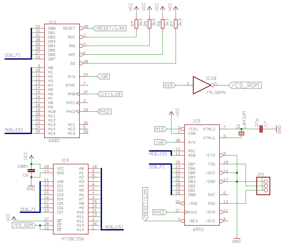
Image

Since the 6507 has only 12 bits of address, my code used is:

Segments
Code:
MEMORY
{
  ROM: start=$2000, size=$2000, type=ro, define=yes, fill=yes, file=%O;
}

SEGMENTS
{
  CODE: load=ROM, type=ro;
  VECTORS: load=ROM, type=ro, offset=$1ffa;
}


Principal Code:
Code:
.setcpu "6502"

                 ACIA_DATA = $0000
                 ACIA_STATUS = $0001
                 ACIA_COMMAND = $0002
                 ACIA_CONTROL = $0003

                 .segment "VECTORS"

                 .word   nmi
                 .word   reset
                 .word   irq

                 .code

reset:           jmp main

nmi:             rti

irq:             rti

main:
init_acia:       lda #%00001011            ;No parity, no echo, no interrupt
                 sta ACIA_COMMAND
                 lda #%00011111            ;1 stop bit, 8 data bits, 19200 baud
                 sta ACIA_CONTROL

write:           ldx #0
next_char:
wait_txd_empty:  lda ACIA_STATUS
                 and #$10
                 beq wait_txd_empty
                 lda text,x
                 beq read
                 sta ACIA_DATA
                 inx
                 jmp next_char
read:
wait_rxd_full:    lda ACIA_STATUS
                 and #$08
                 beq wait_rxd_full
                 lda ACIA_DATA
                 jmp write

text:            .byte "Hello World!", $0d, $0a, $00


Any tips? :cry:
Regards.


Attachments:
captura01.PNG
captura01.PNG [ 2.99 KiB | Viewed 775 times ]
Top
 Profile  
Reply with quote  
PostPosted: Fri Feb 22, 2019 2:53 am 
Offline

Joined: Mon May 21, 2018 8:09 pm
Posts: 1462
So - a 6551. Exactly which 6551 is it? The "latest genuine" WDC parts have a nasty hardware bug, though I don't think that's what you're seeing here.

Also, 19200 baud is near the limit of the 6551's capabilities. Usually 9600 or 1200 baud are better choices for initial tests.

Make certain both ends are set to the same speed for both transmit and receive (many UARTs can set TX and RX parameters independently). It looks like you're receiving more characters than you sent, which may indicate the receive speed is set too high, or the transmit speed too low. Note also that the values you need to poke into the 6551 depend on the clock speed attached to it (usually a UART has a standard-frequency crystal dedicated for this purpose).


Top
 Profile  
Reply with quote  
PostPosted: Fri Feb 22, 2019 3:23 am 
Offline
User avatar

Joined: Fri Dec 11, 2009 3:50 pm
Posts: 3367
Location: Ontario, Canada
How have you modified the circuit? The 6507 lacks several signals noted in the original diagram (which is intended for 6502).

I think the connections formerly driven by A15 can connect to A12 (as shown). But other wiring questions remain. Also, some of the values declared in the program may need to be changed.

First, please tell us what you've done with the wiring. :)

cheers
Jeff


Attachments:
homecomputer-6502-v5-acia-schematic  .png
homecomputer-6502-v5-acia-schematic .png [ 90.63 KiB | Viewed 768 times ]

_________________
In 1988 my 65C02 got six new registers and 44 new full-speed instructions!
https://laughtonelectronics.com/Arcana/ ... mmary.html
Top
 Profile  
Reply with quote  
PostPosted: Fri Feb 22, 2019 11:40 am 
Offline

Joined: Wed Dec 05, 2018 7:52 pm
Posts: 48
Hello guys,

Well answering the questions, I tested with baudrate of 1200 and 9600 and kept getting trash on the way out. I am using as clock source, a crystal of 1.8432 MHz connected in pins 6 and 7 of 6551.

Answering Dr Jefyll, since the 6507 only has addressing up to A12, I connected this port to 6551 as if it were the A15 of 6502. Another replacement I did was that, instead of the AT28C256, I'm using the AE29f2008-12 which is a memory flash removed from a PC BIOS. The pinning is very similar to the AT28C256.

The other ROM address pins are disconnected, as A13, 14 and 15.

What can be wrong? :roll:


Top
 Profile  
Reply with quote  
PostPosted: Fri Feb 22, 2019 12:04 pm 
Offline

Joined: Mon May 21, 2018 8:09 pm
Posts: 1462
The unused ROM input lines must be tied definitely either high or low, not left floating. This is generally true of all CMOS inputs, even of spare gates on a multi-gate 74-series chip. Having not done that, there is a good chance the ROM is confused about what addresses the CPU is requesting.


Top
 Profile  
Reply with quote  
PostPosted: Fri Feb 22, 2019 1:37 pm 
Offline

Joined: Wed Dec 05, 2018 7:52 pm
Posts: 48
Dr Jefyll wrote:
Also, some of the values declared in the program may need to be changed.

cheers
Jeff


What values may need to be changed?


Top
 Profile  
Reply with quote  
Display posts from previous:  Sort by  
Post new topic Reply to topic  [ 128 posts ]  Go to page Previous  1 ... 4, 5, 6, 7, 8, 9  Next

All times are UTC


Who is online

Users browsing this forum: No registered users and 10 guests


You cannot post new topics in this forum
You cannot reply to topics in this forum
You cannot edit your posts in this forum
You cannot delete your posts in this forum
You cannot post attachments in this forum

Search for:
Jump to: