The Cactus, A Starting Point
-
BigDumbDinosaur

- Posts: 9426
- Joined: 28 May 2009
- Location: Midwestern USA (JB Pritzker’s dystopia)
- Contact:
-
CommodoreZ

- Posts: 28
- Joined: 09 Apr 2018
- Location: Z Labs
- Contact:
Re: The Cactus, A Starting Point
I'm in the process of putting together a more centralized page about the Cactus than I've had before: http://www.commodorez.com/cactus.html
I'm also in the process of preparing to exhibit it at Vintage Computer Festival East XIII in Wall, NJ. While it obviously is a new project, the driving spirit has very much been that of the 1970s homebrew scene. Thus, it gets a pass.
In the meantime, I'm weighing a handful of reasonable features to focus on for display purposes. I imagine plenty of time will be spent letting folks play with BASIC, or trying to toggle short programs directly into memory. Worst case scenario, I just swap between EPROMs -- I added the ZIF socket precisely for this reason.
One thought that occurs to me to make my life easier is to have the EPROM's reset vector point to 0x0000 for user entered programs for fun, and the NMI vector point to the start of the serial routine for BASIC. That way I can hook it into the unused half of the step switch, and jump right into BASIC. I tried instead pointing the reset vector to 0x0000 and whenever the user wanted to use BASIC simply enter JMP 00 FF, but it didn't want to take correctly. It would always start, then get locked up shortly thereafter.
I'm also thinking about how exactly I need to re-arrange the bus enable and run lines to best accommodate the single step operation. As it stands, while the machine is halted, the front panel is granted control. That means a single step pulse trying to let the processor do its thing is encountering contention from the front panel logic. I think I'm going to split the RUN/HALT and BUS ENABLE single lines into two separate entities, but I'm still figuring out a game plan here. Again, not the end of the world if I don't get this up and running in time for VCF East.
Lastly, I scored 2KB of NVRAM, and decided it would be worth adding into the mix in lieu of proper secondary storage. For the moment, it will do.
I've got a long to-do list here... but atleast I can say I've played Lunar Lander in BASIC on hardware I built!
- Attachments
-

Re: The Cactus, A Starting Point
Thumbs up for Lunar Lander! It's using a computer for computing, and it's a physical simulation, and it's a game - it's even got lots of historical interest.
-
GARTHWILSON

- Forum Moderator
- Posts: 8773
- Joined: 30 Aug 2002
- Location: Southern California
- Contact:
Re: The Cactus, A Starting Point
CommodoreZ wrote:
Worst case scenario, I just swap between EPROMs -- I added the ZIF socket precisely for this reason.
http://WilsonMinesCo.com/ lots of 6502 resources
The "second front page" is http://wilsonminesco.com/links.html .
What's an additional VIA among friends, anyhow?
The "second front page" is http://wilsonminesco.com/links.html .
What's an additional VIA among friends, anyhow?
-
CommodoreZ
- Posts: 28
- Joined: 09 Apr 2018
- Location: Z Labs
- Contact:
Re: The Cactus, A Starting Point
I've been slacking on making updates here, so I might as well.
VCF East XIII was a blast. People really liked the Cactus, despite it not being a vintage computer.
I ended up just swapping EPROMs as the day went. If I had 32K EPROMs on hand, I would have used the upper/lower bank switching jumper to move between BASIC and direct user data entry. For a time on the second exhibit day, I hooked up an external pulse generator in as a replacement for the 1MHz clock, and slowed down the 65C02 down to the point where you could watch individual opcodes go by. That was fun.
I didn't have any hardware faults from the Cactus itself for the duration of the weekend. My H89 (acting as an H19) stood in as my era-appropriate terminal, and it blew a few fuses from the extended use. I had too small of a fuse value in there anyway, so it's not like anything on the H89 failed.
After coming back, I started overhauling the single step circuitry. I was trying to implement what I was provided by Thrashbarg a few months ago, while integrating my bus arbitration logic to keep the CPU and front panel from causing contention. After hitting a few snags in re-arranging stuff to accommodate the new bus signal, I was able to get 1MHz mode running again, but single stepping just wasn't panning out.
So I did something drastic. I threw together my original idea from late last year of how I figured single step might be done, and bypassed the previous approach by putting READY at +5v. This includes my bus enable + CPU asset lockout logic. Admittedly, it's crude, but it does seem to work... sometimes. 1MHz selection is fine, but single step only works on programs that don't involve using 6850. It starts working and then gets lost part way through as if it lost it's place, if that makes any sense. If I was using an NMOS 6502, I would immediately suspect that the registers were degrading and losing their place, but I'm not so that can't be it.
I've received some Rockwell 6551's in the mail (not the CMOS version as far as I can tell). I was thinking of trying out building a serial card using one of these. I would like to find the version that crams two UARTs into one chip, but these will do for now. I don't suppose anyone has a good example of how to implement the 6551 I can look at to get a better understanding of what's going in in both wiring and software. I think I understand most of the pinouts on this chip, minus how the clock inputs operate. I'm so used to doing the clock divisions myself with the 6850, so I'm going to have to learn how to do this one differently.
I've also been researching how to handle doing audio cassette storage. At this time it isn't a high priority. I realize there are far more reliable and practical methods of data storage, but I want to try my hand at implementing one of the more ubiquitous secondary storage options of the 1970s.
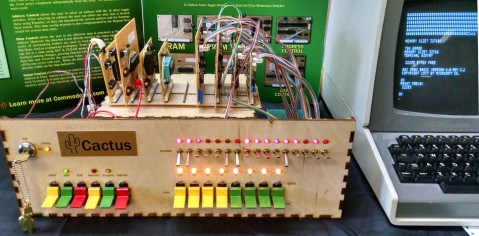
One of the questions that kept coming up at VCF East was "where did you get your front panel switches?" They mean the painted C&K 7205J4 paddle switches to be specific. I got the last 19 they had available on electronic goldmine a few years ago. I quested for more of those switches, only to discover that while the mechanisms are still being manufactured, the plastic J4 and J5 paddles have been out of production for quite some time. Bogus. There is good news though! NKK makes close approximations: M2018TYW01-HA. They have a bit of a stiffer click, but they work. The silver locking toggle switches I had been using aren't very high quality, so I opted to order some NKK replacements as well. I'm ordering all the switches and LEDs I need to make a second front panel, this time out of metal.
I want something more polished because I will be attending VCF West at the Computer History Museum, August 4th & 5th in Mountain View, California. That means flying the Cactus cross country. I figure the more professional it looks, and the more durable it is, the less problems it will give me in transit.
Sorry for the wall of text. I'm probably forgetting something, but I've already been writing this for an hour. I leave you with a photo of Lunar Lander running on the Cactus.
Edits: typo fixes.
- Exhibit front and center
- Exhibit with visitors
- Thrashbarg's suggestion.
- 6502ss tb2.png (7.97 KiB) Viewed 6674 times
- Step select logic
- step select logic.PNG (7.93 KiB) Viewed 6674 times
I've received some Rockwell 6551's in the mail (not the CMOS version as far as I can tell). I was thinking of trying out building a serial card using one of these. I would like to find the version that crams two UARTs into one chip, but these will do for now. I don't suppose anyone has a good example of how to implement the 6551 I can look at to get a better understanding of what's going in in both wiring and software. I think I understand most of the pinouts on this chip, minus how the clock inputs operate. I'm so used to doing the clock divisions myself with the 6850, so I'm going to have to learn how to do this one differently.
I've also been researching how to handle doing audio cassette storage. At this time it isn't a high priority. I realize there are far more reliable and practical methods of data storage, but I want to try my hand at implementing one of the more ubiquitous secondary storage options of the 1970s.
One of the questions that kept coming up at VCF East was "where did you get your front panel switches?" They mean the painted C&K 7205J4 paddle switches to be specific. I got the last 19 they had available on electronic goldmine a few years ago. I quested for more of those switches, only to discover that while the mechanisms are still being manufactured, the plastic J4 and J5 paddles have been out of production for quite some time. Bogus. There is good news though! NKK makes close approximations: M2018TYW01-HA. They have a bit of a stiffer click, but they work. The silver locking toggle switches I had been using aren't very high quality, so I opted to order some NKK replacements as well. I'm ordering all the switches and LEDs I need to make a second front panel, this time out of metal.
I want something more polished because I will be attending VCF West at the Computer History Museum, August 4th & 5th in Mountain View, California. That means flying the Cactus cross country. I figure the more professional it looks, and the more durable it is, the less problems it will give me in transit.
Sorry for the wall of text. I'm probably forgetting something, but I've already been writing this for an hour. I leave you with a photo of Lunar Lander running on the Cactus.
Last edited by CommodoreZ on Sun Jun 17, 2018 7:20 am, edited 1 time in total.
Re: The Cactus, A Starting Point
Excellent! It may not be vintage, but it's certainly retro.
-
GARTHWILSON
- Forum Moderator
- Posts: 8773
- Joined: 30 Aug 2002
- Location: Southern California
- Contact:
Re: The Cactus, A Starting Point
CommodoreZ wrote:
So I did something drastic. I threw together my original idea from late last year of how I figured single step might be done, and bypassed the previous approach by putting READY at +5v. This includes my bus enable + CPU asset lockout logic. Admittedly, it's crude, but it does seem to work... sometimes. 1MHz selection is fine, but single step only works on programs that don't involve using 6850. It starts working and then gets lost part way through as if it lost its place, if that makes any sense. If I was using an NMOS 6502, I would immediately suspect that the registers were degrading and losing their place, but I'm not so that can't be it.
Quote:
I've received some Rockwell 6550's in the mail (not the CMOS version as far as I can tell). I was thinking of trying out building a serial card using one of these. I would like to find the version that crams two UARTs into one chip,
That's the 65c52. They seem to be quite rare. I've never seen one, but the data sheet is in my Rockwell book, as well as on this site, at http://6502.org/documents/datasheets/ro ... _dacia.pdf .
Quote:
but these will do for now. I don't suppose anyone has a good example of how to implement the 6550 I can look at to get a better understanding of what's going in in both wiring and software. I think I understand most of the pinouts on this chip, minus how the clock inputs operate. I'm so used to doing the clock divisions myself with the 6850, so I'm going to have to learn how to do this one differently.
(Note: It's the 6551, not 6550.) See the 6502 primer page on I/O ICs at http://wilsonminesco.com/6502primer/IO_ICs.html for hardware connections. I have some of the software stuff in the 6502 interrupts article at http://wilsonminesco.com/6502interrupts/#3.1 . Although I wish a couple of the control functions had been separated (which would require another register-select bit for more registers), the fact remains that the only trouble I ever had with it was when I lacked a capacitor at a clock pin. Softwarewise, I have never had a bit of trouble with the '51. Every effort was met with success on first try. A few of the tips in my "Tip of the Day" topic on this forum relate to the '51.
Quote:
I've also been researching how to handle doing audio cassette storage. At this time it isn't a high priority. I realize there are far more reliable and practical methods of data storage, but I want to try my hand at implementing one of the more ubiquitous secondary storage options of the 1970s.
Here's a link to search results for topics with the word "tape" in the titles on this forum: search.php?keywords=tape+&terms=all&aut ... mit=Search .
For something more modern yet simple, I like the I2C-6 I²C connector we come up with here on the forum, and for SPI, I like the SPI-10 connector. Both of these are very compact, very hobbyist-friendly and perfboard-friendly, and are very suitable for small, home-made modules using these interfaces. Several members here on the forum have incorporated them into their SBC designs. You can see a half-postage-stamp-sized SPI-10 flash module on the front page of my site, linked below. The 24c__ family of I²C serial EEPROMs in 8-pin DIPs goes up to 32KB in normal addressing, otherwise 128KB in one IC, IIRC. The 25VF___ and 26VF___ families of SPI flash memories in 8-pin SOIC packages was up to 8MB the last I checked which may have been a couple of years ago. These are much cheaper, faster, smaller, and more reliable for data storage than tape, and easy to use. Maybe just not quite as fun. A problem with cassette machines though is that the belts rot (and to a lesser extent, rubber wheels and the pinch roller get hard or may even crack); so even if you thought you had a good cassette machine in a closet, if you get it out and try it you'll probably find it doesn't work. There are places to get new belts though. If you get that far, I might be able to help. I just got new belts for one this year myself.
http://WilsonMinesCo.com/ lots of 6502 resources
The "second front page" is http://wilsonminesco.com/links.html .
What's an additional VIA among friends, anyhow?
The "second front page" is http://wilsonminesco.com/links.html .
What's an additional VIA among friends, anyhow?
Re: The Cactus, A Starting Point
Those were nice photos. Nice display.
Re: The Cactus, A Starting Point
Cactus spotted in this VCF East video - see 16:30 mark here:
https://youtu.be/dOVYrucHBSg?t=16m29s
https://youtu.be/dOVYrucHBSg?t=16m29s
- Attachments
-
-
CommodoreZ
- Posts: 28
- Joined: 09 Apr 2018
- Location: Z Labs
- Contact:
Re: The Cactus, A Starting Point
65c52! That's right, thank you. I will keep an eye out for one in my travels. The typo on the 6551 has been fixed now... that's going to be the one I focus on.
I've seen modern storage alternatives, but the whole point of the project was to explore the intentionally inconvenient. I'm not going to pretend that the Cactus will ever have any sort of practical application, so I might as well play with the classic technologies that interest me most. Thank you for the power search, I will dig through that. For the moment, I've been looking through historical references including a cassette interface related to Microtek, and another from the Compukit UK101 (that rebrand/modification of an OSI machine). I've got a robust Texas Instruments Program Recorder tape deck to use with that part of the project when the time comes. In my research, I've discovered that people seem to love the Kansas City Standard, and others loathe it due to the harmonic tones it uses. I still haven't made up my mind about it...
The NMOS 6502's clock threshold is precisely why I opted for the CMOS version with the static core.
The hackaday article is exciting, and I'm very thankful for Tom taking the time to talk with me at the show. I lost my composure at work when I found out -- excitement abounds. Wait, my exhibit was mentioned in the Guru Meditation video? Awesome, thank you for pointing that out.
So here's what's coming up for the Cactus: I will be exhibiting at VCF West on August 4th & 5th in Mountainview, CA. The following week, I will be giving a talk and demonstration at the DEFCON Hardware Hacking Village at 4PM on August 11th. Then in September, I will probably be exhibiting at VCF Midwest on September 15th & 16th in Chicago, IL. If they have room for me in the schedule, I may also be giving a talk. I've been preparing a proper padded pelican case for air travel to those events.
Edit: included time of DEFCON talk.
-
CommodoreZ
- Posts: 28
- Joined: 09 Apr 2018
- Location: Z Labs
- Contact:
Re: The Cactus, A Starting Point
I've made a bit of progress here and there...
I decided it was time I took a crack at adding a VIA into the mix. Specifically, a 65C22 (although I do have some NMOS ones on hand too). I figured it would be easiest to start simple, and wire up just wire up Port A. I threw an LED on there, and after reading through someone's code on their first steps with a 6522, I was able to devise a simple little test program to get it to blink -- nothing fancy.
By the way, I find it really fun to toggle in a program like this. Sure, it does take a bit of time, but it makes me happy to see an LED controlled by something I built up from scratch.
I've decided that I need to add a bank of 8 programmable LEDs, and find a way to connect up the SET side of the data switches to an input bank on the VIA. I want to program in the classic "kill the bit" game, like you might find on an Altair 8800 or IMSAI 8080. The way the front panel logic was designed on the Cactus, there are lockouts that prevent user interaction with data or address control switches while the CPU is running. I need to make sure inputs like this aren't going to interfere with the data control card, but the concept seems like it will be worth while to implement. I don't know where I'm going to put the LEDs on the panel though... that will probably have to wait until the next revision.
- 65C22 board
Code: Select all
0000        LDA #$FF        A9 FF
0002        STA $A603       8D 03 A6
0005        LDA #$00        A9 00
0007        STA $A601       8D 01 A6
000A        LDX #$C8        A2 C8
000C        LDY #$00        A0 00
000E        DEY             88
000F        BNE $0E         D0 FD
0011        DEX             CA
0012        BNE $0C         D0 F8
0014        LDA #$FF        A9 FF
0016        STA $A601       8D 01 A6
0019        LDX #$C8        A2 C8
001B        LDY #$00        A0 00
001D        DEY             88
001E        BNE $1D         D0 FD
0020        DEX             CA
0021        BNE $1B         D0 F8
0023        JMP $0005       4C 05 00
- blinking
-
CommodoreZ
- Posts: 28
- Joined: 09 Apr 2018
- Location: Z Labs
- Contact:
Re: The Cactus, A Starting Point
So I've made a few tweaks to the 6522 board. I've added a second set of headers, and made a little LED test connector. Next I've got to try my hand at using it for inputs.
It's fun, and useful! I didn't expect it to be that easy to control, either in BASIC or in machine language. I tested it first with assembly, and I'm slowly getting my feet wet in a realm I've never truly felt comfortable in. It's been like 9 years since I did any sort of assembly programming. Up until now, I've just been copying what I see, but this marks a turning point.
Having this kind of programmable output was essential in debugging my 6551 implementation.
It took a little while to find that the source of the issues I was having was a combination of DSR and DCD lines that were not tied to ground, and a terminal that doesn't want to obey 9600 8-N-1. Had to find other devices the Cactus could talk to. It was rather frustrating, I spent a few days on the 6551 issues, and wasn't making any headway until I had some help from Thrashbarg.
After the core hardware of the 6551 board was worked out, I moved over to the seemingly gargantuan task of modifying the serial routines for BASIC's serial interface. Added some initialization code, tweaked the address locations of registers, modified bitmasks where appropriate, and was incredibly surprised to find that it worked. Huh. Didn't think it would work.
I'm still deciding how I want to approach the cassette storage problem. One thing at a time, I suppose.
- 6522 board
- blinkenlights
- dual 6551 board
After the core hardware of the 6551 board was worked out, I moved over to the seemingly gargantuan task of modifying the serial routines for BASIC's serial interface. Added some initialization code, tweaked the address locations of registers, modified bitmasks where appropriate, and was incredibly surprised to find that it worked. Huh. Didn't think it would work.
I'm still deciding how I want to approach the cassette storage problem. One thing at a time, I suppose.
-
CommodoreZ
- Posts: 28
- Joined: 09 Apr 2018
- Location: Z Labs
- Contact:
Re: The Cactus, A Starting Point
It's been awhile, here's the latest in the Cactus updates. You'll forgive me if I copy my text from elsewhere, as I've typed this up like... 6 times by now.
Better yet, I video evidence of the event!
https://youtu.be/K5faZwQoVQc
Then the following week, I talked at DEFCON in the Hardware Hacking Village about the Cactus, the history of the front panel interface, and the rare examples of the 6502 + front panel. I had a small crowd of interested folks, a surprising amount were familiar with the 6502.
Oh, and while I was out in Nevada, I took the Cactus out to the desert and took some pictures with it. We found a little prickly pear (I think). For the record, the Cactus was running on battery when these photos were taken. It was just doing a NOP + JMP loop.
Why? Because it was fun!
But on a more serious note, the rigorous testing has pointed out a few tweaks I need to make in the status control card's sequencing logic. The data flip flops aren't blanking when they should, showing I need to rework the timing and logic chain. The result is that each byte that is copied to the 8 flip flops is ORed with the previous byte. I've got less than a month before VCF Midwest in Chicago to get that squared away.
- MOnSter + Cactus Mashup
Quote:
I exhibited the Cactus at VCF West on August 4th & 5th in Mountain View California, at the Computer History Museum. This was my first time at VCF West, and the atmosphere made for a different experience compared to VCF East. The Cactus was transported in a customized flight case to ensure it arrived intact. However, due to poor packing on my part, the contents shifted on its 3000 mile journey. The Deposit switch and a pair of header pins on the Status Control card were damaged in transport, and required on-site repairs before the show began. Fortunately, I was able to effect repairs, and the rest of the weekend's demonstrations went smoothly.
A few weeks prior to the show, I discovered that the MOnSter 6502 would be in attendance, along with the good folks at Evil Mad Scientist Laboratories. I reached out to its creator, Eric Schlaepfer, and asked if he would be willing to combine our two machines in an experiment. He was interested, letting me know that as long as I adhered to the NMOS specification and clocked down to 50KHz, the two should be able to work together. Normally, the Cactus relies on the 65C02's Bus Enable pin to halt the CPU and allow the front panel logic to take over to provide the user with direct memory access. I built a new processor card with additional buffers to account for the lack of such a pin on the NMOS variant, and tested it with an original Commodore 6502 from 1983.
Once at VCF West, our first attempt on Saturday pointed out that I had neglected to buffer the Read/Write line, resulting in bus contention. On Sunday, Eric brought me a breadboard, some additional jumper wires, and a few tristate buffers from his stockpile. After splicing an additional 74LS245 into the NMOS card, and testing with an NMOS 6502, we decided to try again. Lo and behold, the Cactus and the MOnSter 6502 successfully booted into BASIC, and ran at 50KHz for about half an hour, creating a spectacular fusion of blinkenlights. That makes the Cactus the third machine to use the MOnSter 6502, and the first one that wasn't made by Eric. Needless to say, this was the highlight of my weekend.
- closeup
Better yet, I video evidence of the event!
https://youtu.be/K5faZwQoVQc
Then the following week, I talked at DEFCON in the Hardware Hacking Village about the Cactus, the history of the front panel interface, and the rare examples of the 6502 + front panel. I had a small crowd of interested folks, a surprising amount were familiar with the 6502.
- defcon talk
- cactus twice!
- me with the cactus
But on a more serious note, the rigorous testing has pointed out a few tweaks I need to make in the status control card's sequencing logic. The data flip flops aren't blanking when they should, showing I need to rework the timing and logic chain. The result is that each byte that is copied to the 8 flip flops is ORed with the previous byte. I've got less than a month before VCF Midwest in Chicago to get that squared away.
Last edited by CommodoreZ on Tue Aug 21, 2018 8:26 pm, edited 1 time in total.
Re: The Cactus, A Starting Point
Excellent result - thanks for the writeup, photos and video!
(I do believe I see an OSI300 remake on the table too... these fairs and conventions are great for seeing the variety of projects and products old and new.)
(I do believe I see an OSI300 remake on the table too... these fairs and conventions are great for seeing the variety of projects and products old and new.)