It has been a busy month, but I did get a day to work on the board last week.
Since the new Sync Generator is fully software programmable, I decided to experiment with different video modes.
At 640x480, these are somewhat limited, since it is only the vertical resolution that can be altered.
So, at 25MHz, 640x480 or 640x240 are really the only options, but that aspect ratio is not much good.
I have also been battling some serious capacitance issues with my clock routing at this speed.
So much so that, I had to "tune" some of the clock lines using a variable resistor!
A non-breadboard layout would certainly work later on, but these glitches will make testing very difficult.
During my latest experimentation, I went back to 20MHz, and revisited the 800x600 VGA mode.
At 20MHz, the horizontal resolution is fixed to 400, but there are decent vertical options available.
The system can now do 400x600 (default mode), 400x300, or even 400x200.
Actually, the vertical can be divided to any number whatsoever.
Just like the Amiga, multiple modes can be delivered on one screen.
A demo may have a 400x600 title at the top, but then do fast graphics at 400x300 in the center screen.
At 400x600 with 4096 colors, the images looks as good as 640x480, but there are no clock speed issues at all.
Seems that 20MHz is the "safe" zone for my giant breadboard, with 25Mhz being right at the razor's edge!
During my testing, I had to rewire most of the address lines, and alter a lot of once tidy wiring...
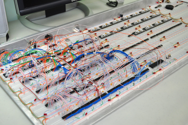 This is what it looks like before I clean up the wires.
So now I am working out the details on the new Graphics Generator, which will command 4 MB x 16 Bits of fast SRAM.
This will be my most complex version yet, and I am hoping for 10 MHz or better performance. (I had 4 MHz last time).
Having such limited time, it is easy to forget what the hell I was doing, so I have started making schematics.
Here is the VGA Output Stage, which is just a simple circuit that aligns everything on the Master Clock...
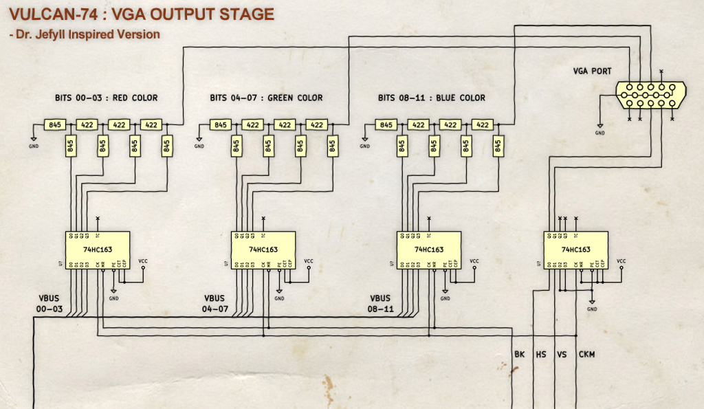 VGA Output Stage.
VBUS : 12 Bit Video Data Bus
CKM : Master Clock (20MHz)
BK : Blanking Signal
HS : Horizontal Sync
VS : Vertical Sync
I originally used 74HC08 AND gates to sync the data to the clock, but I was bullied into trying 163 counters instead.
... and whadda ya know, it saved one extra chip! Kudos Jeff!
I will drill downward on the other parts of the schematic and post them when I have the time.
The Graphics Generator is only in "I think it will work" stage, so it will be wired up soon.
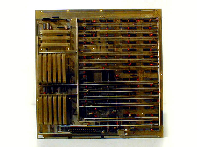
Notice all of the SRAM taking up the right side of the board. 16 chips in total (512K x 8).
At 400x300 resolution, a bitmap could be 34 screens in size! That's a HUGE scrolling background.
This memory will contain all Sprites as well as Background Images, but it's still a lot of room to work.
I have also come up with a proposed Cartridge Loading System, which will use a clocked 8 Bit input system.
Loading of the first 64K segment will happen automatically on startup, and then the 6502 will do the rest.
Once the 6502 Boot Program is loaded, the CPU can then access over 4 gigs of storage space.
Yeah... I am including a 32 bit address system to the cartridge!
Just think of the crazy power I am handing out to the 6502 now...
- 400 x 600 VGA with 4096 simultaneous Colors
- 4 MB of ultra high speed Graphics / Sprite Memory
- High speed "transparent aware" Blitter System
- 4 Voice digital stereo sample Sound System
- 4 Gigabyte capable external Cartridge Loader
- Super Nintendo compatible dual Joystick Ports
It's kind of like dropping a Model-T Ford engine into a Testarossa, but the 6502 deserves it!
Cheers!
Radical Brad