I had a problem where the system would work correctly if PHI2 was 1 Hz or slower (single-stepping) however when PHI2 was any faster (even 10 Hz) I was seeing $ff on the data bus when there should have been other values whenever NVRAM was being read. I have some very weak pull-ups on the data bus so I suspect that it wasn't being driven when the NVRAM was selected. After some head scratching I noticed this:
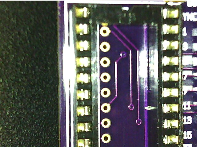
The socket pin seventh down on the right hand side was bent when it was inserted in to the PCB for soldering.
That pin is /OE for the NVRAM and was supposed to wired to GND. The NVRAM was being programmed at 115,200 baud without issue but could only be read very sedately. After I patched that up, it worked just fine at 1 MHz.
I could have saved some time in this case had I e-tested my boards after assembly. Is there any way a hobbyist can take the drudgery out of an e-test? Some sort of flying probe on a 3-axis machine perhaps? Or maybe a program that organizes then steps through the netlist, shows what should be tested and then automatically proceeds when it gets continuity?


