(first post, so be nice!)
I am working on a small 65C02 based SBC, using some elements that are similar to a number of other 6502.org members approach of using a PIC/AVR to provide bootloading of the ROM.
I had a question about the timing requirements as it relates to a memory write. Assume I am talking only about the WDC65C02, not the older MOS 6502s.
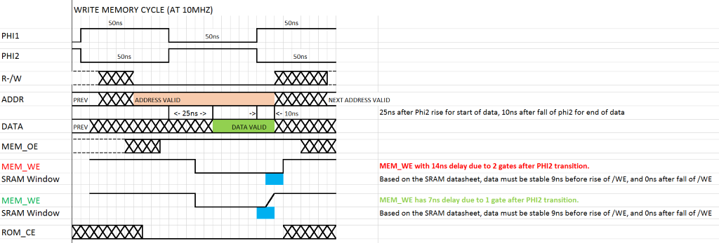
First, a simple timing diagram. Increments (cells) are 5ns apart.

In looking at the datasheet for the 65C02, during a write cycle the output data lines are guaranteed to be active and valid at least 30ns before the fall of phi2, and 10ns after the fall of phi2. That is represented in the diagram in green. These are minimum values, and there are no listed maximum values.
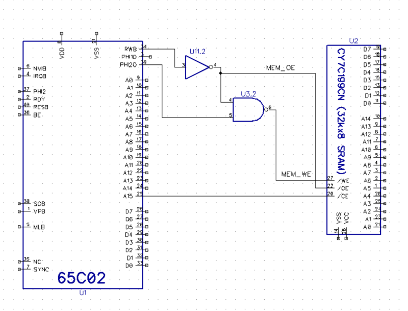
Consider the simple (incomplete, just for discussion) circuit below:

Let's assume for discussion that propagation delay through a gate is 7ns. (74HCT)
In this circuit, the /WE pin on the SRAM is controlled by the NAND of Phi2 and /RWB (inverted RWB). That is also represented in the first timing diagram as MEM_WE in green. In this configuration, when Phi2 transitions happens, the SRAM will see the rising of /WE 7ns later. For this particular SRAM, the data has to be valid 10ns before the /WE rising transition, and 0 (ZERO) ns after the transition. In this case, there would be no problem. The SRAM effectivly clocks the data on the rising edge of /WE, but needs no hold over ( I would assume due to internal propagation in the design.)
All is good.
Consider an addition where I want to be able to read and write from that same SRAM via my PIC controller while the CPU is paused. Assume for this conversation that the CPU can be paused, and the BE raised such that the 65C02 will tristate it's output pins.
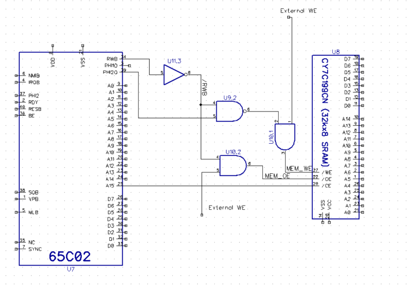
I first proposed the following circuit:

In this circuit, I added an additional AND gate in front of both the MEM_WE and MEM_OE signals. This would allow these external lines to control the memory (by going to 0), or let the CPU signal pass through (by going to 1). The downside of this approach is that it adds an additional gate delay to the signal AFTER the falling edge of Phi2. This is represented in the timing diagram as MEM_WE red. Since the two gates would add up to 14ns of delay, the rising edge of MEM_WE that the SRAM sees will happen 4 ns after the CPU data lines could potentially go invalid.
It is possible that this might just work, as the 10ns of data hold time is the minimum listed in the 65C02 datasheet... but I have no experience to say if that is true. It is interesting that this effect is not related to cpu clock speed, as the 10ns data hold time is a fixed value (at 5V)s. The only limitation is the delay from PHI2 to the SRAMs /WE.
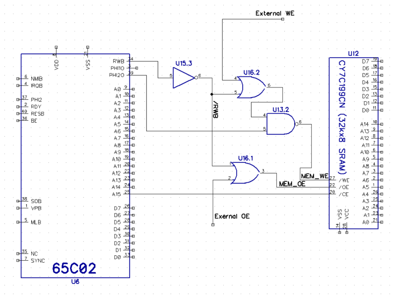
An alternate fix is to consider this:

In this circuit I have moved the external AND gates behind the gates that mix in Phi2. In this case the falling edge of PHI2 is only delayed by one gate (7ns), thus the memory write pattern should work correctly. The only problem is that for this design to work, the 65C02 must be paused with the PHI2 in the high state, and the External OE and WE are inverted ( 0 - pass through, 1 - PIC assert ).
Is there anything obvious that I am missing here?
Jeff


