6502.org Forum  Projects  Code  Documents  Tools  Forum
It is currently Sat Sep 21, 2024 2:56 am

All times are UTC


Post new topic Reply to topic  [ 11 posts ] 
Author Message
PostPosted: Fri May 09, 2014 10:24 pm 
Offline
User avatar

Joined: Sun Sep 08, 2013 10:24 am
Posts: 740
Location: A missile silo somewhere under southern England
Hi guys

I've been jumping back and forth between projects recently, one of which is fixing old 8 & 16 bit micros that I've purchased. Whilst looking at the circuit digram for my BBC Micro B (6502 CPU) I noticed that the data bus is pulled to ground through 8x 6k8 resistors.
I noticed that in most 6502 designs this is not done.

Does anyone know why one would do this in the first place? I can understand doing it if you suspect that an input is possibly going to be left high impedance, but I don't think that's the case here. I ask because I'm curious and if I need to think about putitng this in my design.

I can supply the circuit diagram for the BBC model B if needed.

Cheers!


Top
 Profile  
Reply with quote  
PostPosted: Sat May 10, 2014 1:23 am 
Offline
User avatar

Joined: Thu May 28, 2009 9:46 pm
Posts: 8390
Location: Midwestern USA
banedon wrote:
I've been jumping back and forth between projects recently, one of which is fixing old 8 & 16 bit micros that I've purchased. Whilst looking at the circuit digram for my BBC Micro B (6502 CPU) I noticed that the data bus is pulled to ground through 8x 6k8 resistors.

Without seeing the schematic I'm only guessing that the 6.8K resistors are there to minimize ringing problems.

_________________
x86?  We ain't got no x86.  We don't NEED no stinking x86!


Top
 Profile  
Reply with quote  
PostPosted: Sat May 10, 2014 8:02 pm 
Offline
User avatar

Joined: Thu Dec 11, 2008 1:28 pm
Posts: 10938
Location: England
Indeed, I think it's a bus termination tactic: when some pins at one of a bus change state, the whole bus doesn't change at once; rather, there's a wave of voltage change which moves along the bus, like a wiggle in a skipping rope. If the end of the rope offers no means of damping, there'll be a reflection when the wiggle reaches the end, which comes back along the rope. In the case of the bus, this means the voltage doesn't just move smoothly to the new value, it overshoots.

Cheers
Ed


Top
 Profile  
Reply with quote  
PostPosted: Sat May 10, 2014 8:23 pm 
Offline
User avatar

Joined: Fri Aug 30, 2002 1:09 am
Posts: 8510
Location: Southern California
Indeed strange. If it's for termination at all, I'd have to say it was minunderstood by the designer, because the characteristic impedance of the line being terminated (if indeed there even is a valid transmission line with a true ground plane) wil be much, much lower than 6.8K, meaning 6.8K won't have a significant effect against ringing. Pulling to ground wouldn't really be the best way to do it anyway, since NMOS and LSTTL outputs (if indeed there is any LSTTL on the board) can't pull up nearly as hard as they can pull down, and LSTTL (or any kind of TTL) inputs take a lot more to pull them down than up.

_________________
http://WilsonMinesCo.com/ lots of 6502 resources
The "second front page" is http://wilsonminesco.com/links.html .
What's an additional VIA among friends, anyhow?


Top
 Profile  
Reply with quote  
PostPosted: Sun May 11, 2014 5:57 am 
Offline
User avatar

Joined: Thu Dec 11, 2008 1:28 pm
Posts: 10938
Location: England
Hmm. This is a bit beyond me.

As I understand it, there are oddities in the Beeb's circuit design, and it's quite a marginal design. One thing to note is that the databus is available to take off-board, unbuffered, as part of the second-processor (Tube) interface. See the bottom left of
http://www.8bs.com/boards/BBCBschematicJTribbeck.png
(via http://www.8bs.com/insides.htm#circuit)

I checked the service manuals at
http://acorn.chriswhy.co.uk/docs/Acorn/ ... 5_Sec1.pdf
http://acorn.chriswhy.co.uk/docs/Acorn/ ... 5_Sec2.pdf
but there's nothing to help - other than to confirm the 6k8 value.

Notably, at http://www.acornelectron.co.uk/eug/50/a-24bb.html where Robert Sprowson suggests a design for expanding an Acorn Electron, he suggests a 3k3 symmetric termination - that would be an effective 1k7, I think.

Cheers
Ed


Top
 Profile  
Reply with quote  
PostPosted: Sun May 11, 2014 12:49 pm 
Offline
User avatar

Joined: Mon Apr 23, 2012 12:28 am
Posts: 760
Location: Huntsville, AL
It appears that the consensus is that 6k8 ohm pull down resistors are not there for termination of a transmission line. It is too high a resistance to have an impact on any signal reflections that may exist on the bus during normal operations.

As others have indicated, the current input into a TTL input pin, usually implemented with NPN Bipolar Junction Transistors (BJTs) and associated with logic high input signals, is significantly lower than the current output from a TTL input pin, i.e. a logic low input signal. TTL gates also exhibit a greater signal range associated with a logic high, 2.6V (2.4V ... 5V), than they do for a logic low, 0.8V. These two factors should lead most designers to implement pull ups for most signals when using TTL.

Non TTL-compatible CMOS logic exhibits much more symmetric signal ranges for logic high and low values; typically around 1V for a logic high and 0.8V for a logic low. The complementary nature of the insulated gate Field Effect Transistors (IGFETs) used for the input pin in CMOS logic also means that the magnitude of the currents into and out of CMOS logic input pins are much lower than those for TTL. Thus, with CMOS logic it is more reasonable to see busses pulled high or pulled low, especially with high value 6k8 ohm resistors.

I prefer to pull busses high primarily because the resistance required is much higher. This means that during normal operations, the average current supplied by the pull up resistors is much lower. To ensure that the steady state logic low value is less than 0.8V, a significantly lower pull down resistor is needed which results in much higher operating currents. The higher operating current needs of a pulled down bus does not contribute much to signal integrity, and it can negatively impact the transition time of signals because less current is available to charge/discharge the line capacitance.

Sometimes pull down termination is unavoidable, but I think that pull up termination is preferred.

One reason to passively terminate a bus is to ensure that if there are no "responders" to a bus transaction, the default value of the bus is a halt code of some sort. The instruction set of most microprocessors was not designed with this in mind. When would the processor ever be made to read a non-existent address? :) 
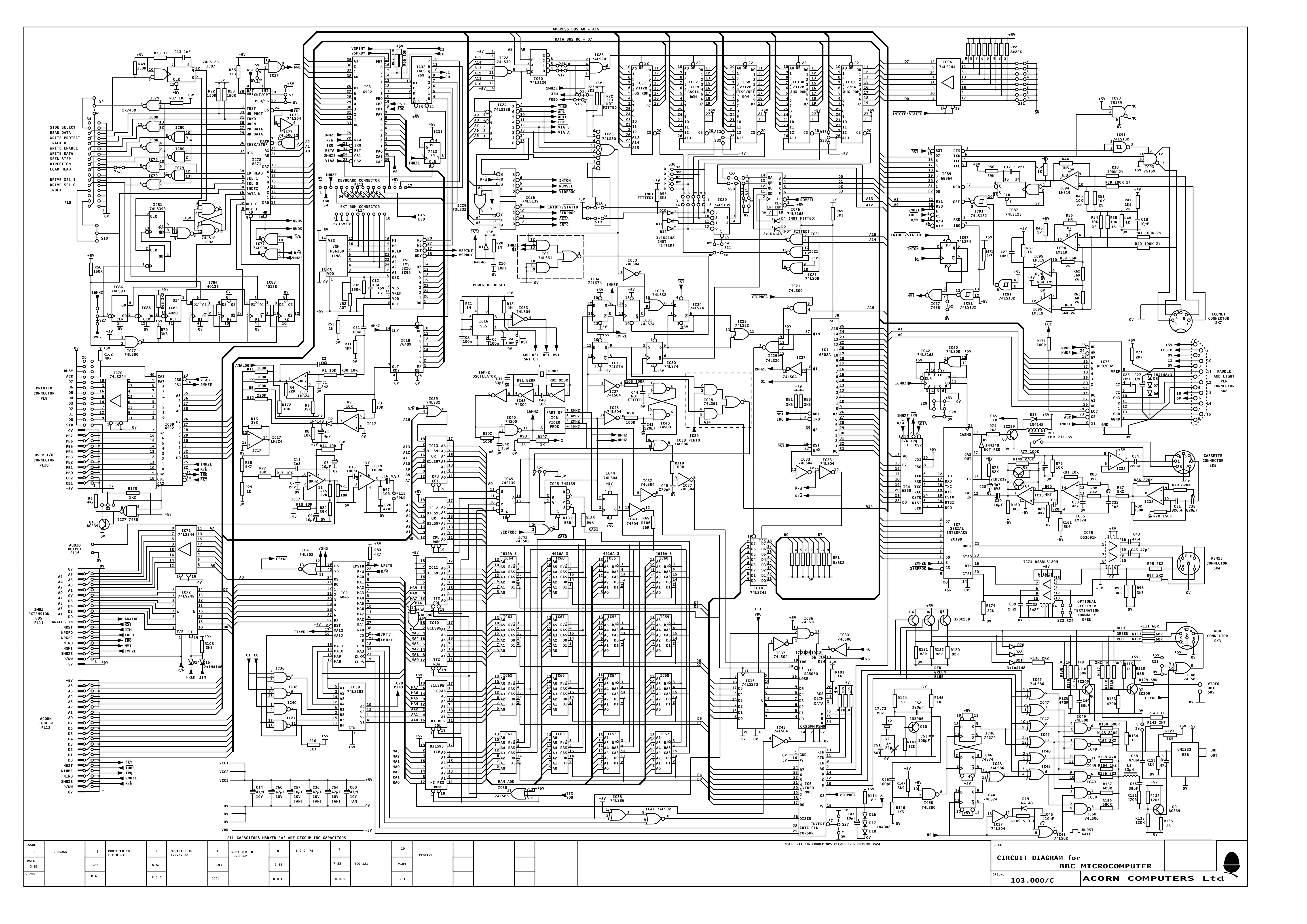
However, the opcode for the BRK instruction of the 6502 is 0x00. This may be reason enough to pull the bus down. If the processor attempts to read instructions from unimplemented memory, the pull down resistors will yield a BRK opcode. A BRK trap subroutine could then be used to map out installed memory and I/O devices.

I don't expect that this is the use in your computer of the pull down resistors. However, it is also possible to achieve this type of behavior by using pull ups and inverting bus transceivers. In many early systems, you will find that many busses where implemented using inverting bus drivers, i.e. PDP 11 Unibus and others. In many of those early systems the halt code was a logic 0. In addition, TTL inverters use one less transistor in the output signal path. This makes the inverting buffer faster than the non-inverting buffer.

_________________
Michael A.


Top
 Profile  
Reply with quote  
PostPosted: Sun May 11, 2014 4:33 pm 
Offline
User avatar

Joined: Fri Dec 11, 2009 3:50 pm
Posts: 3367
Location: Ontario, Canada
banedon wrote:
I ask because I'm curious and if I need to think about putting this in my design.
I think you can safely omit this feature in your design, banedon. :) But it is intriguing -- thanks for bringing it to our attention.

As noted, the resistors' value is too high for them to act as termination. I think MichaelM has a much better theory regarding the resistors' function: to establish a default value if there are no "responders" to a bus transaction.

The intent may be to detect whether a given address region is populated -- say, with an optional memory or I/O expansion card. System software could either jump to the region in question (and possibly execute a BRK as Michael suggests) or it could do a "look before you leap" maneuver that involves an exploratory LDA (for example), or several, from the region in question. If the result is zero then we conclude the optional expansion card is not installed.

Alternatively, I can imagine these resistors as part of an I/O scheme that uses diodes (rather than tristate drivers) to place data on the bus. I know that sounds wonky, but unusual circumstances can lead to unusual solutions, and this may be a case in point. Unfortunately I don't know enough about the Beeb to guess what "circumstances" might lead to this. Would you oblige us, please, Banedon, by posting that schematic?

cheers
Jeff

_________________
In 1988 my 65C02 got six new registers and 44 new full-speed instructions!
https://laughtonelectronics.com/Arcana/ ... mmary.html


Top
 Profile  
Reply with quote  
PostPosted: Tue May 13, 2014 6:18 pm 
Offline
User avatar

Joined: Mon Dec 08, 2008 6:32 pm
Posts: 143
Location: Brighton, England
Dr Jefyll wrote:
Alternatively, I can imagine these resistors as part of an I/O scheme that uses diodes (rather than tristate drivers) to place data on the bus. I know that sounds wonky, but unusual circumstances can lead to unusual solutions, and this may be a case in point. Unfortunately I don't know enough about the Beeb to guess what "circumstances" might lead to this. Would you oblige us, please, Banedon, by posting that schematic?


The Beeb has no diode-resistor logic in its design. I think the resistors are there to pull the bus to a defined state when the Beeb tries to access a non-existant device. This would happen, for example, on boot-up when the MOS scans the sideways ROMs to determine which sockets have valid ROMs in them.

_________________
Shift to the left,
Shift to the right,
Mask in, Mask Out,
BYTE! BYTE! BYTE!


Top
 Profile  
Reply with quote  
PostPosted: Tue May 13, 2014 6:41 pm 
Offline
User avatar

Joined: Thu Dec 11, 2008 1:28 pm
Posts: 10938
Location: England
Good spot! You're exactly right. I had a one-line ROM inspector which was showing that (some time ago) and I didn't understand why.
Code:
@%=3:FORY%=0TO15:P."ROM: ",Y%:FORI%=&8000TO&8007:?&F6=I%:?&F7=I%DIV256:A%=USR(&FFB9)AND&FF:P.~A%;:N.:P.:N.


Top
 Profile  
Reply with quote  
PostPosted: Thu Mar 26, 2015 4:34 pm 
Offline
User avatar

Joined: Sun Sep 08, 2013 10:24 am
Posts: 740
Location: A missile silo somewhere under southern England
Sorry to resurrect an old thread, but I think I've found a (non-) explanation for this.
Have a look at the following youtube video. It's worth watching in its entirety, but the explanation is at 9:30
https://www.youtube.com/watch?v=y4WG549i3YY

To jump to the right part of the video:
https://www.youtube.com/watch?v=y4WG549i3YY#t=9m30s


Top
 Profile  
Reply with quote  
PostPosted: Thu Mar 26, 2015 5:19 pm 
Offline
User avatar

Joined: Thu Dec 11, 2008 1:28 pm
Posts: 10938
Location: England
Good find! It's notable that the successor, the BBC Master, has a less-loaded bus which is buffered before it leaves the PCB to external peripherals, and has a symmetric termination which is a bit more as expected. It also has a CMOS CPU. (Another successor, the B+, has the bus loading sorted, has an NMOS CPU, but lacks any termination as far as I can tell.)


Top
 Profile  
Reply with quote  
Display posts from previous:  Sort by  
Post new topic Reply to topic  [ 11 posts ] 

All times are UTC


Who is online

Users browsing this forum: No registered users and 7 guests


You cannot post new topics in this forum
You cannot reply to topics in this forum
You cannot edit your posts in this forum
You cannot delete your posts in this forum
You cannot post attachments in this forum

Search for:
Jump to: