
Hi, all.
DRC2 is a 6502 based single board computer.
Memory map and connector pinout are supposed to be
compatible to Daryl's SBC2.
There also is a TTL based monochrome CRT/LCD controller for the computer.
It can display 320*200 graphics and 40*25 text simultaneously.
Link:
http://www.6502.org/users/dieter/drc2/drc2.htm
DRC2: a 6502 based single board computer
-
BigDumbDinosaur

- Posts: 9428
- Joined: 28 May 2009
- Location: Midwestern USA (JB Pritzker’s dystopia)
- Contact:
Re: DRC2: a 6502 based single board computer
ttlworks wrote:
Hi, all.
DRC2 is a 6502 based single board computer.
Memory map and connector pinout are supposed to be
compatible to Daryl's SBC2.
There also is a TTL based monochrome CRT/LCD controller for the computer.
It can display 320*200 graphics and 40*25 text simultaneously.
Link:
http://www.6502.org/users/dieter/drc2/drc2.htm
Wow! Looks pretty darn good. I was a bit surprised to see Rockwell parts though.
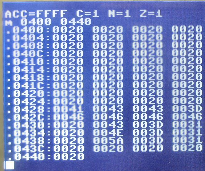
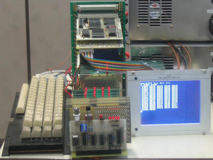
How about some screen shots of the display?
x86? We ain't got no x86. We don't NEED no stinking x86!

Re: DRC2: a 6502 based single board computer
Impressive! After playing around with discrete TTL video a little, I can appreciate the effort your display board must have taken.
Nice work. I look forward to hearing more about your designs.
Daryl
Nice work. I look forward to hearing more about your designs.
Daryl
Please visit my website -> https://sbc.rictor.org/
Re: DRC2: a 6502 based single board computer
BigDumbDinosaur wrote:
Wow! Looks pretty darn good. I was a bit surprised to see Rockwell parts though.
those PCB layouts.
I just had those Rockwell parts sitting in the drawer for more than 20 years.
Where I live, the 6502 and its peripherals are not considered to be
"standart parts" by most distributors.
Quote:
How about some screen shots of the display?
controller during my old M02 and MT15 CPU projects.
The D04 CRT/LCD controller is based on the D03 concept, and makes a similar picture,
so I think the old D03 related screen shots will do.
http://6502.org/users/dieter/mt15/mt15_cpu_right.jpg

Re: DRC2: a 6502 based single board computer
Nice! I see Mike's already added this to the http://www.6502.org/homebuilt/ page.
Re: DRC2: a 6502 based single board computer
8BIT wrote:
Impressive! After playing around with discrete TTL video a little,
I can appreciate the effort your display board must have taken.
I can appreciate the effort your display board must have taken.
I'm using a 15 bit counter (2*74LS393) running at 1 MHz
plus a 27512 EPROM which contains a lookup table
for generating display address and control/sync signals.
What made the design a bit complicated is, that the CRT/LCD controller
has its own clock, means it runs independent from the 6502 clock.
The CRT/LCD controller passively snoops the 6502 bus for write cycles,
and holds them in a temporary latch (3*74LS574) to mirror memory writes
into its own 32 kB RAM.
Quote:
Nice work. I look forward to hearing more about your designs.
After some years of absence from hobby electronics,
I needed something for getting started again.
And to me, the SBC2 concept looked best for this purpose.
-
ElEctric_EyE
- Posts: 3260
- Joined: 02 Mar 2009
- Location: OH, USA
Re: DRC2: a 6502 based single board computer
I had to post just to say hello and thanks for posting here.
Dieter, I believe you're the one who did a hardware 6502 made of discrete TTL components?
Very impressive when I read it years ago!
Welcome back to your hobby. Looking forward to more of your machines.
Dieter, I believe you're the one who did a hardware 6502 made of discrete TTL components?
Very impressive when I read it years ago!
Welcome back to your hobby. Looking forward to more of your machines.
Re: DRC2: a 6502 based single board computer
ElEctric_EyE wrote:
I had to post just to say hello and thanks for posting here.
Quote:
Dieter, I believe you're the one who did a hardware 6502 made of discrete TTL components?
Very impressive when I read it years ago!
Very impressive when I read it years ago!
M02 used a concept which was completely different from the 6502:
it wasn't timing compatible, lacked decimal mode,
used a somewhat crude form of microcode,
had EPROMs which contained lookup tables to work as ALU,
etc. ...
...but yes, it was TTL and it did run 6502 machine code.
Quote:
Welcome back to your hobby. Looking forward to more of your machines.
I'm still rebooting, please don't expect anything "spectacular" for 2013.
Re: DRC2: a 6502 based single board computer
Hi @ttlworks,
I have a question about the video card that you have built as a part of DRC2 computer. In short I was looking at the LCD connector schematic and I cannot understand how can I use it with a TFT LCD screen.
I was expecting something like a three control lines CLK, HSYNC, VSYNC and more lines with raw pixel data. On the connector on the other hand I can see some other signals like FRM and BAS.
So far I suspect that QVS and QHS are just different names for VSYNC and HSYNC lines and that XCLK is obviously the clock signal. But what is FRM, BAS and QPIX? That I cannot understand.
I knew that you are a busy person and that perhaps you have forgotten the details - if you cannot answer this question then that would be OK too.
I really want to thank you for designing this computer and open sourcing the schematics. It is really a huge help for hobbyists like me.
Re: DRC2: a 6502 based single board computer
Hi 0xmarcin.
Welcome to our forum, and thanks for the kind words.
I had used a monochrome 320*240 LCD (without a LCD controller already integrated, quite rare these days).
There seems to be no standard for that sort of displays when it comes to pinout and signal naming conventions.
The solution was to have a small adaptor PCB between the controller and the LCD to compensate for the different pinouts.
Actually, my HSYNC\VSYNC signal timing doesn't _exactly_ match the specifications for analog video TV and 320*240 LCD,
I just had "tinkered with the timing" until I had a stable picture on the TV and the LCD at the same time...
BTW: where I live, 50Hz VSYNC and 15.625kHz HSYNC is the standard for analog video.
;---
"BAS (Bild-Austast-Synchron)" is German for VBS "(Video Blanking Sync)",
BAS is an analog composite video signal output (without the chrominance) to be fed into a TV or a monitor.
;
If it's a cheap monitor which doesn't properly clamp the analog video signal to the black level,
resulting in brightness going "off track" when having big areas of white on the screen,
jumper J4 could be used for choppig the video signal with the dot clock for (hopefully) improving the situation.
//Got that trick from the NKC.
For monitors with TTL level input signals (in the "good old days" there were such things),
QPIX is the digital video signal, QVS is VSYNC, QHS is HSNYC. //The 'Q' denotes an output.
Since there isn't exactly a standart for the polarity of such TTL level monitor signals, there are jumpers for changing signal polarity by using XOR gates.
For the LCD:
QVS is VSYNC, QHS is HSYNC.
FRM is a control signal which toggles after every frame (IC29B on page 8 in the d04v1.sch schematics), the display needed that control signal.
;
XCLK is the clock signal, R7 (470 Ohm to GND) is there to dampen line reflections on the wire to the LCD.
//Note, that XCLK is gated with "display enable", the display needed that clock gating.
;
XD3..0 is the 4 Bit monochrome video data.
//Data for the pixels is transmitted in 4 Bit "chunks" with XCLK being the clock.
BTW: when building that D04 display controller years ago, I didn't know about 6502 bus timing what I know by now.
Hope, this helps.
You happen to have a datasheet\specification for the TFT LCD screen you are out to use ?
Edit:
Speaking about LCDs, the screenshot up in the thread is from a Hosiden HLM8620-12.
IIRC Seiko\Epson TCM-A0635-1 also had worked.
Maybe I had tried other LCDs before using these two (this would explain that FRM signal), but I don't remember anymore.
Last edited by ttlworks on Mon Sep 28, 2020 8:41 am, edited 1 time in total.

Re: DRC2: a 6502 based single board computer
Hallo Dieter,
Very nice system!
Could the part that generates VSYNC, HSYNC, etc. signasl be tweaked so one could attach a VGA monitor?
Very nice system!
Could the part that generates VSYNC, HSYNC, etc. signasl be tweaked so one could attach a VGA monitor?
Code: Select all
    ___
   / __|__
  / /  |_/     Groetjes, Ruud
  \ \__|_\
   \___|       URL: www.baltissen.org
Re: DRC2: a 6502 based single board computer
Hallo Ruud,
The IBM specification for VGA says: VSYNC 50..70Hz, HSYNC 31.5kHz.
So for keeping the screen resolution we had at 15.625kHz HSYNC, for VGA the dot clock needs to be at least twice as fast.
IMHO making the display controller VGA capable would require a complete redesign, sorry to say this.
BTW: for the asynchronous 74LS393 counters feeding the ROM which contains the lookup table for display control, 1MHz seems to be the speed limit.
When making a redesign, I would suggest to build a better 6502 bus interface by using 74377 clocked with PHI2... but 74377 has no output enable.
Re: DRC2: a 6502 based single board computer
Thank you ttlworks for a very detailed answer. I guess I got all that I needed. I plan to first use a cheap RCA/composite -> VGA converter (the kind used to connect security cameras to computer screens), they are very cheap and support variety of inputs. I am hoping that since your TV was able to display the signal this device would recognise it too and convert it to a usable (higher res) VGA.
Finding a suitable LCD may indeed be a problem, but I am not in hurry. Maybe I will manage to find something suitable on Mouser or AliExpress...
Ruud, at first I had exactly the same thought, it would be nice to generate just VGA input. After Ben Eater posted his breadboard video card (https://eater.net/vga), a lot of people are trying to create a usable TTL video card. I myself was thinking about using a dual-port RAM with Ben's design, but these are not only hard to find but also either too small (2K) or too expensive... Good for text, but not so for graphics...
Re: DRC2: a 6502 based single board computer
Please define your "too small" versus "too expensive" ratio:
Dual port RAMs at Mouser, prices from September 2020:
IDT7132LA35PDG 2kB 35ns PDIP48, 11.07€
IDT7142LA20JG 2kB 20ns PLCC52, 13.96€
IDT7134LA25JGI 4kB 25ns PLCC52, 16.19€
IDT7005L15JG 8kB 15ns PLCC68, 23.71€
IDT7006L20JGI8 16kB 20ns PLCC68, 30,82 €
IDT7007L15JG 32kB 15ns PLCC68, 39.45€
IDT7008L15JG 64kB 15ns PLCC84, 51.29€
IDT7009L20PFGI 128kB 20ns PQFP100, 66.17€
Hmm... for those who dare:
CY7C25632KV18-450BZXI 4M*18 450ps FBGA165 1.8V, 188.18€
CY7C25652KV18-400BZXC 2M*36 450ps FBGA165 1.8V, 199.22€
Just kidding.
-
BigDumbDinosaur
- Posts: 9428
- Joined: 28 May 2009
- Location: Midwestern USA (JB Pritzker’s dystopia)
- Contact:
Re: DRC2: a 6502 based single board computer
ttlworks wrote:
Hmm... for those who dare:
CY7C25632KV18-450BZXI 4M*18 450ps FBGA165 1.8V, 188.18€
CY7C25652KV18-400BZXC 2M*36 450ps FBGA165 1.8V, 199.22€
Just kidding.
CY7C25632KV18-450BZXI 4M*18 450ps FBGA165 1.8V, 188.18€
CY7C25652KV18-400BZXC 2M*36 450ps FBGA165 1.8V, 199.22€
Just kidding.
x86? We ain't got no x86. We don't NEED no stinking x86!