6502.org Forum  Projects  Code  Documents  Tools  Forum
It is currently Sat Nov 23, 2024 11:52 pm

All times are UTC


Post new topic Reply to topic  [ 15 posts ] 
Author Message
PostPosted: Tue Jul 02, 2013 8:26 pm 
Offline

Joined: Tue Jul 02, 2013 2:23 am
Posts: 10
Hi there, this is my first post, so bear with me :)

I'm in the process of designing a PCB for a design using 65xx chips and had a question about the pullup resistors for the interrupt pins. I'm using the free version of Eagle so board space is pretty limited. In order to save some room and components, I was planning on using a single pullup resistor for IRQ, NMI, and BE (i'm using a WDC 65c02). Would that be acceptable? Alternatively, could I just tie them all to 5V, since I don't plan on using them?

Thanks!


Top
 Profile  
Reply with quote  
PostPosted: Tue Jul 02, 2013 9:06 pm 
Online
User avatar

Joined: Fri Aug 30, 2002 1:09 am
Posts: 8546
Location: Southern California
Welcome.

Most people here would leave BE tied high; but ruling out any use of NMI and IRQ would put a rather severe limit on what you can do with the computer.  If you do ever plan to use them, tying them together would not be a good thing either.  If you give each one its own pull-up resistor, at least you leave the option of using the inputs later.  See my 6502 interrupts primer.  The interrupt-connections page of my 6502 primer is at http://wilsonminesco.com/6502primer/IRQconx.html .

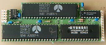
If board space on the free version of Eagle is that much of a problem, you could put the pull-up resistors on the back of the board, opposite an IC.  Actually this board uses interrupts:
Attachment:
SymCPU.jpg
SymCPU.jpg [ 18.45 KiB | Viewed 216 times ]

(It has the ROM on the back of the board.)  This board is shown near the bottom of the page on address decoding.  Address decoding can be done much more simply than beginners tend to do, and you might save some parts (and room) there.  The schematic of this board is very similar to the first schematic on the circuit potpourri page.

_________________
http://WilsonMinesCo.com/ lots of 6502 resources
The "second front page" is http://wilsonminesco.com/links.html .
What's an additional VIA among friends, anyhow?


Top
 Profile  
Reply with quote  
PostPosted: Tue Jul 02, 2013 9:14 pm 
Offline
User avatar

Joined: Mon Apr 23, 2012 12:28 am
Posts: 760
Location: Huntsville, AL
Since you are going to the trouble of making a PCB, I would tie NMI and BE to VDD and PU IRQ with resistor.

_________________
Michael A.


Top
 Profile  
Reply with quote  
PostPosted: Tue Jul 02, 2013 9:41 pm 
Offline

Joined: Tue Jul 02, 2013 2:23 am
Posts: 10
GARTHWILSON wrote:
Welcome!

Most people here would leave BE tied high; but ruling out any use of NMI and IRQ would put a rather severe limit on what you can do with the computer. If you do ever plan to use them, tying them together would not be a good thing either. If you give each one its own pull-up resistor, at least you leave the option of using the inputs later. My interrupts primer is at http://6502.org/tutorials/interrupts.html . The interrupt-connections page of my 6502 primer is at http://wilsonminesco.com/6502primer/IRQconx.html .

If board space on the free version of Eagle is that much of a problem, you could put the pull-up resistors on the back of the board, opposite an IC. Actually this board uses interrupts:
Image
(It has the ROM on the back of the board.) This board is shown near the bottom of the page on address decoding. Address decoding can be done much more simply than beginners tend to do, and you might save some parts (and room) there. The schematic of this board is very similar to the first schematic on the circuit potpourri page.


Thanks for the reply! Also, your 6502 primer has been great help thus far!

My project is an extension of the Atari 2600 video game system. If you can believe it, the original design uses a 6507 which does not have any interrupt pins other then reset! I agree, it may be silly to rule out the possibility that I would like to use the interrupts in the future. I am literally almost out of space though, and a few resistors may put me over the limit. It is just good to know that if I really need to, I could tie them to 5v.


In case anyone is interested in my project, here's some info. Originally, I just wanted to replace the 6507 with a full 6502 for the extra address space (64K over 8K). In doing some research, I came across the WDC 65C02 and couldn't resist trying to overclock the processor. The Atari 2600 has a very primitive video chip with no video RAM whatsoever. There are just a few registers for colors and sprites that need to be changed on the fly as the electron beam of a television draws each pixel. In other words, about 70% of all the CPU time is spent drawing the screen with very precisely timed code. Overclocking the CPU can mean a tremendous improvement in the graphics you can pull off (and also incompatibility with all existing software :| ). I've also expanded the original 128 bytes or RAM to 16 KB. Here's a thread about the project:

http://atariage.com/forums/topic/201304 ... -wdc65c02/


Top
 Profile  
Reply with quote  
PostPosted: Tue Jul 02, 2013 11:58 pm 
Offline
User avatar

Joined: Thu May 28, 2009 9:46 pm
Posts: 8513
Location: Midwestern USA
Wickeycolumbus wrote:
Hi there, this is my first post, so bear with me :)

Welcome to our little 65xx world.

Quote:
I'm in the process of designing a PCB for a design using 65xx chips...planning on using a single pullup resistor for IRQ, NMI, and BE (i'm using a WDC 65c02). Would that be acceptable? Alternatively, could I just tie them all to 5V, since I don't plan on using them?

As Garth noted, if you proceed as you plan you can't use any of these inputs for anything, and I'm hard-pressed to think of any application where completely eliminating the possibility of using interrupts would make sense. Better to work on your layout to accommodate separate resistors. Garth's suggestion about placing them on the solder side of the PCB should work well. You could also use a SIP resistor package, which takes little space.

Since you mentioned that you will be using the W65C02S please note the following. DO NOT tie RDY directly to Vcc! When the WAI instruction is executed the MPU will pull RDY low. You really don't want to find out just how far the MPU can sink the power supply before it (the MPU) converts itself from a semiconductor to a full-time conductor. RDY should be pulled up to Vcc through a 3.3K resistor (also a good value for other pullups). RDY, along with all other inputs, must not be allowed to float.

Now, you might be saying, "I don't plan on using WAI for anything, so I don't expect anything like that to happen." That's all well and good, except a programming error could inadvertently cause opcode $CB (WAI) to be executed. Incidentally, if WAI is executed and there is no interrupt pending the MPU will stop and remained stopped until something interrupts it.

_________________
x86?  We ain't got no x86.  We don't NEED no stinking x86!


Top
 Profile  
Reply with quote  
PostPosted: Wed Jul 03, 2013 12:56 am 
Offline

Joined: Tue Jul 02, 2013 2:23 am
Posts: 10
BigDumbDinosaur wrote:
Wickeycolumbus wrote:
Hi there, this is my first post, so bear with me :)

Welcome to our little 65xx world.

Quote:
I'm in the process of designing a PCB for a design using 65xx chips...planning on using a single pullup resistor for IRQ, NMI, and BE (i'm using a WDC 65c02). Would that be acceptable? Alternatively, could I just tie them all to 5V, since I don't plan on using them?

As Garth noted, if you proceed as you plan you can't use any of these inputs for anything, and I'm hard-pressed to think of any application where completely eliminating the possibility of using interrupts would make sense. Better to work on your layout to accommodate separate resistors. Garth's suggestion about placing them on the solder side of the PCB should work well. You could also use a SIP resistor package, which takes little space.

Since you mentioned that you will be using the W65C02S please note the following. DO NOT tie RDY directly to Vcc! When the WAI instruction is executed the MPU will pull RDY low. You really don't want to find out just how far the MPU can sink the power supply before it (the MPU) converts itself from a semiconductor to a full-time conductor. RDY should be pulled up to Vcc through a 3.3K resistor (also a good value for other pullups). RDY, along with all other inputs, must not be allowed to float.

Now, you might be saying, "I don't plan on using WAI for anything, so I don't expect anything like that to happen." That's all well and good, except a programming error could inadvertently cause opcode $CB (WAI) to be executed. Incidentally, if WAI is executed and there is no interrupt pending the MPU will stop and remained stopped until something interrupts it.


Thanks :)

Actually, I am using RDY, it is required to interface with the video chip. Thanks for that info though, definitely something I could run into in the future!


Top
 Profile  
Reply with quote  
PostPosted: Wed Jul 03, 2013 8:34 am 
Offline

Joined: Sun Apr 10, 2011 8:29 am
Posts: 597
Location: Norway/Japan
BigDumbDinosaur wrote:
I'm hard-pressed to think of any application where completely eliminating the possibility of using interrupts would make sense.
Probably every application on the OP's target, the Atari 2600.. :) It's very special in that the CPU is almost literally drawing the screen pixel by pixel, changing intensity etc. in real time. Very timing critical, obviously. The leftover time (flyback) is used for actual application processing. I don't know much about the 2600, but there was a link to a youtube video of a talk by one of the more famous game programmers and he explained it in detail. From how he explained it I imagine throwing an interrupt into the mix would be a total disaster.

-Tor


Top
 Profile  
Reply with quote  
PostPosted: Wed Jul 03, 2013 9:30 am 
Online
User avatar

Joined: Fri Aug 30, 2002 1:09 am
Posts: 8546
Location: Southern California
Quote:
From how he explained it I imagine throwing an interrupt into the mix would be a total disaster.

That reminds me of reading about the days back when instructions were coming off a magnetic drum (before discs) in realtime and they tried to place each instruction at the right part of the drum so it would be coming up to the head just as it's needed.

Why not have the interrupt start each line.  When the scan line is finished, the other computing can be done with total timing freedom, possibly yielding enough additional computing power to offset the number of cycles required for the interrupt sequence.

I just read up a little on it.  I was stunned that it had no RAM except the 128 bytes in the 6530 RIOT!

_________________
http://WilsonMinesCo.com/ lots of 6502 resources
The "second front page" is http://wilsonminesco.com/links.html .
What's an additional VIA among friends, anyhow?


Top
 Profile  
Reply with quote  
PostPosted: Wed Jul 03, 2013 10:02 am 
Online
User avatar

Joined: Fri Aug 30, 2002 1:09 am
Posts: 8546
Location: Southern California
Quote:
there was a link to a youtube video of a talk by one of the more famous game programmers and he explained it in detail.

Maybe this one, starting about 38 minutes in? https://www.youtube.com/watch?v=aNyebnxV9R8

_________________
http://WilsonMinesCo.com/ lots of 6502 resources
The "second front page" is http://wilsonminesco.com/links.html .
What's an additional VIA among friends, anyhow?


Top
 Profile  
Reply with quote  
PostPosted: Wed Jul 03, 2013 10:57 am 
Offline

Joined: Sun Apr 10, 2011 8:29 am
Posts: 597
Location: Norway/Japan
That's an interesting video. The one I watched was this one though (managed to find it): https://www.youtube.com/watch?v=MBT1OK6VAIU
David Crane explaining how he wrote the game 'Pitfall' for the Atari 2600, and explaining a lot more at the same time.

-Tor


Top
 Profile  
Reply with quote  
PostPosted: Wed Jul 03, 2013 2:28 pm 
Offline

Joined: Tue Jul 02, 2013 2:23 am
Posts: 10
Processing an interrupt for the start of every line would take up quite a bit of extra CPU time. A lot of games just use the entire time for drawing code. There is a zero 'strobe' register you can hit to wait for the start of the next line, which uses the RDY pin to halt the processor until the line starts.

Now that I think of it, the NMI can be hooked up to a development PC for code upload. There could be a boot ROM with the NMI handler that jumps to code download routines, so you could upload new code with a command line at any point in the testing process, rather than rebooting the system.


Top
 Profile  
Reply with quote  
PostPosted: Wed Jul 03, 2013 5:01 pm 
Offline
User avatar

Joined: Sat Sep 29, 2012 10:15 pm
Posts: 904
There is also a book called "Racing the Beam The Atari Video Computer System (Platform Studies)"

http://www.amazon.com/Racing-Beam-Compu ... 26201257X/

_________________
In theory, there is no difference between theory and practice. In practice, there is. ...Jan van de Snepscheut


Top
 Profile  
Reply with quote  
PostPosted: Fri Jul 05, 2013 9:33 am 
Offline
User avatar

Joined: Mon Dec 08, 2008 6:32 pm
Posts: 143
Location: Brighton, England
GARTHWILSON wrote:
I just read up a little on it. I was stunned that it had no RAM except the 128 bytes in the 6530 RIOT!

Some of the more advanced games (e.g. millipede) included paged RAM and ROM banks in the cartridge to overcome this. The CPU R/W' pin was not connected to the cartridge slot so the cartridge determined whether you were reading or writing RAM based on what address you accessed - you couldn't read RAM at the same address as you wrote to RAM!

_________________
Shift to the left,
Shift to the right,
Mask in, Mask Out,
BYTE! BYTE! BYTE!


Top
 Profile  
Reply with quote  
PostPosted: Fri Jul 05, 2013 10:47 am 
Offline
User avatar

Joined: Thu Dec 11, 2008 1:28 pm
Posts: 10986
Location: England
Indeed - See the exhaustive document by Kevin Horton at http://blog.kevtris.org/blogfiles/Atari ... appers.txt


Top
 Profile  
Reply with quote  
PostPosted: Mon Jul 08, 2013 11:52 am 
Offline

Joined: Tue Jul 02, 2013 2:23 am
Posts: 10
PaulF wrote:
GARTHWILSON wrote:
I just read up a little on it. I was stunned that it had no RAM except the 128 bytes in the 6530 RIOT!

Some of the more advanced games (e.g. millipede) included paged RAM and ROM banks in the cartridge to overcome this. The CPU R/W' pin was not connected to the cartridge slot so the cartridge determined whether you were reading or writing RAM based on what address you accessed - you couldn't read RAM at the same address as you wrote to RAM!


Which of course means that you can't do any instructions like INC on them.

Someone came up with a method a few years ago that allows you to read and write RAM from the cartridge port with a single address without any additional signals but I have no idea how it works.


Top
 Profile  
Reply with quote  
Display posts from previous:  Sort by  
Post new topic Reply to topic  [ 15 posts ] 

All times are UTC


Who is online

Users browsing this forum: No registered users and 73 guests


You cannot post new topics in this forum
You cannot reply to topics in this forum
You cannot edit your posts in this forum
You cannot delete your posts in this forum
You cannot post attachments in this forum

Search for:
Jump to: