Hello everybody,
I hope this is the right place for this topic. In preparation for my own homebrew 6502 system I need a possibility to write data on a 28C64 or eventually the 28C256 EEPROM. I'm quite familiar with the AVR ATMega micro-controllers, especially with the Arduino boards and so I decided to build my own programmer based on the Atmega328 µC.

The 28C64 and 28C256 are 28 pin DIP chips and have up to 14 address lines (28C256). I also need 8 data lines and 3 additional lines for /WE, /OE and /CE. The programmer should be used by a serial connection, so I need 2 more lines for RX and TX.

In sum 27 lines. My preferred µC has only 20 GPIO pins that seems to be too less for my programmer. But for the address-lines I only need output and no input lines so I can use two 74HC595 shift register to get up to 16 address-lines with only 3 GPIOs used on the µC.
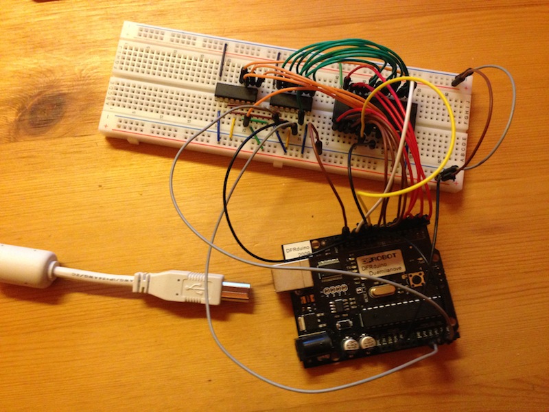
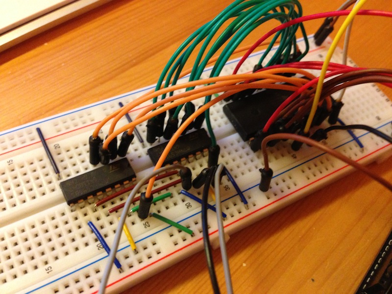
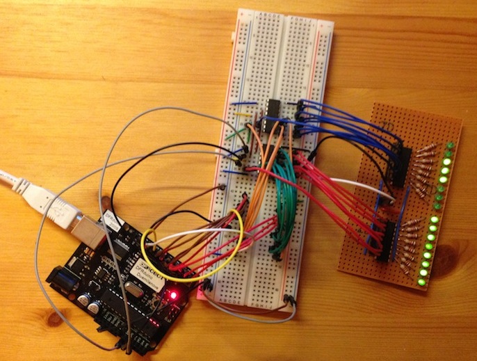
To be sure that everything works as expected, I first build up everything on a breadboard. Additionally I created a simple “16 bit line-sniffer” with 16 small LEDs and two ULN2803 darlington drivers to protect the “sniffed” bus from too much current consumption.
The first thing was to test the output of the address-lines. The Arduino IDE provides a simple function to shift out data to a single IO-line, using a second line as clock. But it's important to push the bytes in the right order and also set the right direction for the single bits (MSB or LSB).
While counting up all possible addresses in a loop, I could check that all 16 bits are shifted out in the right order.

The next thing was to set the data on my 8 bit data bus right. My first idea was to use a complete 8bit GPIO port form the Arduino to simplify reading and writing data. But unfortunately the only complete usable 8bit port on the Arduino board includes also the both serial-ports (RX,TX) that I need for the serial communication. So I had to cut my data byte into 8 bit-pieces setting them one by one to the choosen IO lines. To be sure that everything is connected right I used my little sniffer again read and check the data output. All these things were done without the 28C64 connected to the breadboard.
The next step was to play with the EEPROM itself. As a first step I tried to read the data from the EEPROM with the following procedure
* set databus for reading
* first disable output (/OE HIGH)
* enable chip select (/CE LOW)
* disable write (/WE HIGH)
* set address bus
* enable output (/OE LOW)
* read databus
*disable output (/OE HIGH)
Reading the complete EEPROM returns 0xFF for all bytes, as expected.
The next thing was to write data. There are two modes for writing on my AT28C64. Byte-write and page-write. Because page-write is more complex, I first started with writing single bytes by the following procedure
* first disable output,write and chip select (/OE,/WE,/CE HIGH)
* set address bus
* set data bus
* enable chip select (/CE LOW)
* enable write (/WE LOW)
* wait some micro seconds for the
* disable write (/WE HIGH)
* disable chip select (/CE HIGH)
* wait 10ms for the write cycle to finish
To test this procedure I counted a data byte from 0 to 0xff and wrote every step to the addresses from 0x0000 to 0x0100.
After that I used my reading function to check the written data.
Here is the output of my serial monitor:
Quote:
start writing
finished writing
time elapsed : 2653ms
start reading:
0 : 0 1 2 3 4 5 6 7 8 9 A B C D E F 10 11 12 13 14 15 16 17 18 19 1A 1B 1C 1D 1E 1F
20 : 20 21 22 23 24 25 26 27 28 29 2A 2B 2C 2D 2E 2F 30 31 32 33 34 35 36 37 38 39 3A 3B 3C 3D 3E 3F
40 : 40 41 42 43 44 45 46 47 48 49 4A 4B 4C 4D 4E 4F 50 51 52 53 54 55 56 57 58 59 5A 5B 5C 5D 5E 5F
60 : 60 61 62 63 64 65 66 67 68 69 6A 6B 6C 6D 6E 6F 70 71 72 73 74 75 76 77 78 79 7A 7B 7C 7D 7E 7F
80 : 80 81 82 83 84 85 86 87 88 89 8A 8B 8C 8D 8E 8F 90 91 92 93 94 95 96 97 98 99 9A 9B 9C 9D 9E 9F
A0 : A0 A1 A2 A3 A4 A5 A6 A7 A8 A9 AA AB AC AD AE AF B0 B1 B2 B3 B4 B5 B6 B7 B8 B9 BA BB BC BD BE BF
C0 : C0 C1 C2 C3 C4 C5 C6 C7 C8 C9 CA CB CC CD CE CF D0 D1 D2 D3 D4 D5 D6 D7 D8 D9 DA DB DC DD DE DF
E0 : E0 E1 E2 E3 E4 E5 E6 E7 E8 E9 EA EB EC ED EE EF F0 F1 F2 F3 F4 F5 F6 F7 F8 F9 FA FB FC FD FE FF
It takes about 2.6 seconds to write 256 bytes. Over 96% of the writing time is caused by the 10ms write cycle after setting the /WE pulse. In the datasheet these 10ms are only listed for the “page write” mode, but trying to reduce the waiting time for a “byte write” caused wrong written data. So I have to live with that.
So the fist step is done. The next steps are
* moving from the breadboard to a prototype pcb with a zif socket
* replacing the arduino board with a single atmega328 µC
* creating a serial protocol that can be used easily for burning data to a eeprom
I'll keep you updated in this thread for the next things to come in this little project.
And sure, any additional ideas, tips and hints are welcome


