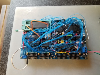
I've reached that annoying part of the process - trying to figure out why the board still doesn't work even though it is (or seems to be) wired up properly!
Attachment:
 20230803_131357.jpg [ 3.55 MiB | Viewed 5870 times ]
So I pulled out my Arduino and my slow clock module and fired up Ben Eater's bus module. Instead of pictures, I made a little video:
https://youtu.be/Oc070ZULVoMThis baroque monstrosity actually runs at 13.5 MHz (yay!) but not 16 MHz (boo! but not unexpected). In the video, for testing purposes, however, the clock module is running at about 3 Hz. The clock stretcher is in place, so the ROM accesses (which is most cycles) are actually about .75Hz. I grabbed a bunch of random LEDs from the drawer; turns out half of them are UV party lights, and two of them are those random blinky fireworks ones, giving my test rig a little more bling than I'd planned!
Edit: Actually, that's not quite accurate. While I was writing that I forgot to take into account that the clock stretcher divides the oscillator frequency by 2. So the VIA is actually running at 1.5Hz, and the ROM accesses are one-fourth of that, roughly 3/8 Hz!
So far I have verified that the OE/WE signals of the RAM and ROM were connected to each other, but not to READ and WRITE.


I think what happened is I was wiring up the control signals, had to break for dinner, thought "OK, after dinner I will finish hooking up READ and WRITE," instead after dinner watched Star Trek, came back the next day and though "OK, yesterday I wired up the control signals, so today I'll do the bus wiring!" Whupps. Anyway, things that actually are working:
1. Reset controller (DS1813) - happy to find I didn't fry it while hooking it up. I had some soldering adventures in that corner of the board.
2. Clock stretcher - It's kind of fun to watch it in slow-mo after a reset. It zips through its internal reset stuff, then hits the brakes when it starts reading from ROM.
3. ROM - reading / executing instructions just fine (now that OE is attached to something!)
4. I/O decoding - the VIA on the breadboard is clocked by the unstretchy Q0 output of the `163; the 6502 is clocked by the stretchable Q2 output.
Next up: put the RAM back in and try running some code with subroutines. (y/n)


