That said, yes, having to write a pile of code for an MCU of a different architecture is rather a pain, and I too prefer to avoid that when I can. Plus I just find it more fun to do fully retro board designs, rather than relying on much more modern stuff for the support system.
Tinker, 6502 in a can.
Re: Tinker, 6502 in a can.
wayfarer wrote:
at this point however, I am not using the MCU, its just too big (too many pins) and a lot of extra work (a whole other architecture!)
That said, yes, having to write a pile of code for an MCU of a different architecture is rather a pain, and I too prefer to avoid that when I can. Plus I just find it more fun to do fully retro board designs, rather than relying on much more modern stuff for the support system.
Curt J. Sampson - github.com/0cjs
Re: Tinker, 6502 in a can.
cjs wrote:
wayfarer wrote:
at this point however, I am not using the MCU, its just too big (too many pins) and a lot of extra work (a whole other architecture!)
That said, yes, having to write a pile of code for an MCU of a different architecture is rather a pain, and I too prefer to avoid that when I can. Plus I just find it more fun to do fully retro board designs, rather than relying on much more modern stuff for the support system.
so normally I think Id put these going the other way, this shows the layout more clearly than the plain side:
Here are several photos of possible options.
Re: Tinker, 6502 in a can.
so there is still a lot missing and I want to go over several designs again, this is however as good a start as any and I am fairly certain this problem I face now is one to solve early.
in this schematic you have right to left:
6502 = RAM = ROM = Generic Display Controller.
I do not have adequate buss control, or clock signals yet I am sure. I am not 100% on ram, rom, or other devices yet, each thing in its own time...
In the bottom right, is 8 buttons, that map to a 'controller' on the front. how do I make that an address in RAM?
I think I need a tri-state buffer/driver, one that is a latch?
a 74xx573 or do I want a 74xx259?
what I am after is when a button is pressed, it latches to an input. polled by the CPU every so often and clears the buffer. this should be the easiest, can be tied to the main loop and screen updates easily and needs the least debounce hardware. I do not want to generate an interrupt and debounce 8 switches, I want to poll the controller like 30 times a second or so. maybe 16 or20.
so, if I have an 8-bit latch tied to a set of 8 buttons, how do i make that byte... $FFF1-FFF2 or whatever that is available to the CPU to read?
Re: Tinker, 6502 in a can.
i mean a VIA would make connecting some buttons pretty easy
but since you want to use discrete logic, you can do it like the NES. which only latches the controller inputs when the CPU wants to read them.
though the NES controller used a shift register because it send the data over a serial line. in your case all buttons are directly on the PCB so you could get away without a latch and just use a simple tri-state buffer (and maybe some debouncing circuitry). the buffer would be enabled whenever the CPU reads from a specific address, which depends on how your logic is built.
i'd recommend putting all your IO in roughly the same area, for example 256 bytes directly at the start of your ROM (let's say $C000-$C0FF). that would mean your decoding logic checks if the upper 8 bits of the address bus are equal to $C0, and if true generate a single "IO Enable" signal which you can use with the lower 8 bits of the address bus to see which IO decide specifically is being addressed. that way you decode IO Addresses in 2 steps, with the upper 8 bits taken care of by a single comparator, so you only need to worry about the bottom 8 bits per IO device, which makes the logic a bit easier if you have multiple IO devices. (at the expense of some propagation delay)
atleast that's how i do it on my SBCs!
ok now i need to ask what is happening with the address bus on your ROM in that schematic. specifically A0 on the ROM is connected to the CPU's A15. and the CPU's A0 is not connected at all.
i assume that's a small mistake, because that would causes the CPU to access the ROM out of order.
for example if the CPU reads from Address $FF00, then $FF01, then $FF02, it would map to address $7F01 twice, and then to $7F03.
so yea, you'd want the ROM's Address lines to directly match the CPU's. A0->A0, A1->A1, etc. same with the data lines.
On a side note, with RAM it doesn't matter how you order the address or data lines when connecting to the CPU, it will still work perfectly fine. so for those you can map the lines however it fits best with your routing.
Re: Tinker, 6502 in a can.
wayfarer wrote:
what I am after is when a button is pressed, it latches to an input. polled by the CPU every so often and clears the buffer. this should be the easiest, can be tied to the main loop and screen updates easily and needs the least debounce hardware. I do not want to generate an interrupt and debounce 8 switches, I want to poll the controller like 30 times a second or so. maybe 16 or20.
It will probably easier not to have the buttons latch when they are pressed but instead just let their state be their state, whatever it is when you scan them. (That also saves you the trouble of releasing the latch.) None of the systems I've examined do any debouncing at all, so it seems that as long as you're scanning the buttons frequently enough, but not too frequently, everything there is fine. You don't even need to deal with anything related to key rollover if you're just doing a small set of buttons that are individually pressed at relatively long intervals compared to typing. (Some of the 8-bit systems, such as the 6800-based Hitachi Basic Master series, do not support key rollover anyway, essentially not scanning for any new keys until all old keys are lifted IIRC, which is annoying to fast typists like me but still usable I suppose.)
If you want to study some hardware and code that uses this technique, I've done a fair amount of reverse-engineering on the Commodore 16 Keyboard Hardware/Firmware, which uses a 6529 Single Port Interface (essentially, a stripped-down, one port version of a 6520 PIA) to set which row to scan and a latch in the TED chip to read the columns from that row. Your system would be simpler, of course, needing just the latch. Their firmware code is relatively long and complex as it does mapping of key codes to PETSCII, maintains a buffer of recently typed characters and so on; you might find extracting the scanning code from my slightly simpler stand-alone program ted-keymatrix.a65 easier. (That program shows the keyboard matrix on the screen and indicates when keys are being pressed, and uses a slightly different scanning algorithm.)
Quote:
so, if I have an 8-bit latch tied to a set of 8 buttons, how do i make that byte... $FFF1-FFF2 or whatever that is available to the CPU to read?
I would start with Address Decoding from the Wilson Mines 6502 primer. Once you've digested that, I cannot strongly enough recommend examining and understanding the address decoding on some existing systems such as Grant's 7-chip 6502 computer, tebl's SBC, and a few others, perhaps including a commercial computer or two such as the Commodore PET. Note that you don't need to restrict yourself to 6502 systems here; Motorola 6800 and 6809 systems will be substantially similar, and 8080/Z80 systems differ only in having ROM in the low addresses and a second 256-byte address space often used for I/O devices.
I suspect the simplest system will be to reduce your ROM to 16K and have your display at $8000-$9FFF and buttons at $A000-$BFFF. (Or if you need more ROM and less RAM, reduce RAM to 16K and put your display at $4000-$5FFF and buttons at $6000-$7FFF.) Design this out to get a sense of how it works. If you want to get much more complex than that, you'll probably start to see why people like to use PLAs, CPLDs or microcontrollers emulating devices for this sort of thing.
Curt J. Sampson - github.com/0cjs
Re: Tinker, 6502 in a can.
Controller: (input decoding stuff)
I am greatly tempted to add a VIA. more later.Yes, in fact not going through the serial line that makes things slightly different, because of this certain chips just wont work, even though they have a reset/clear function and 8x tristate outputs...
Just using a simple Latch/Buffer is probably ok., yet it has its own challenges. I have a choice of several chips. the 74573 is pretty simple as a 'gate', its just a single pin and the 'data side' goes to the 6502.. I think this might be easy to wire up maybe...
Ultimately, yes, just like an NES controller, this device has only 8 input buttons, mapped to a specific address in RAM, one bit for each button, up.down.left.right.red.blue.yellow.green. I will discuss use of a VIA below.
This is roughly the way keyboard scanning works on many '70s and '80s 8...gotcha, I am not putting a full keyboard on here, it will be an onscreen menu, like a game or industrial machine. Just 8 buttons as mentioned. This is to keep it simple and minimize complexity and hardware connections. one of my next builds will have a calculator keypad and additional buttons.
So the trouble here is 'missing' an input because of operator timing, when you are playing a game, and you push a button, you should not push it several times and hope it connected; so I am thinking a latch and some software says if held down or hit repeatedly. There is a buffer and it actually looks simple and not too bad, its in the picture below, the 74'573. It just needs two control pins, more on that below. It would just 'expose the pins' when told to, so addressing on that just needs to turn everything off and let it be on the data buss... not too bad I think
On a future project yes, this is such a deep dive for this, its beyond the scope of an altoids can.
I only have a few devices, keypad and screen... I might sack a byte to output to a sound chip... again, a VIA here is attractive. I am moving to an 8k EEPROM, it frees up control lines and simplifies things, I would be placing I/O just below that or just above RAM.
so here it seems I can or should do that, though exactly how was not lining up as expected. the design below is much cleaner.
Address Decoding: latches and buffers and gates oh my!
And there's the rub: now you're into dealing with address decoding. I mentioned this earlier, but I suspect you didn't fully understand it, or at least its implications. In your current schematic I note that the chip selects for your RAM, ROM and display are all unconnected; you need to have an address decoding system that deals with all of these, too, as well as your button interface.yes this is the part I am trying to sort out. The 6502 doesn't have any Chip Select lines.
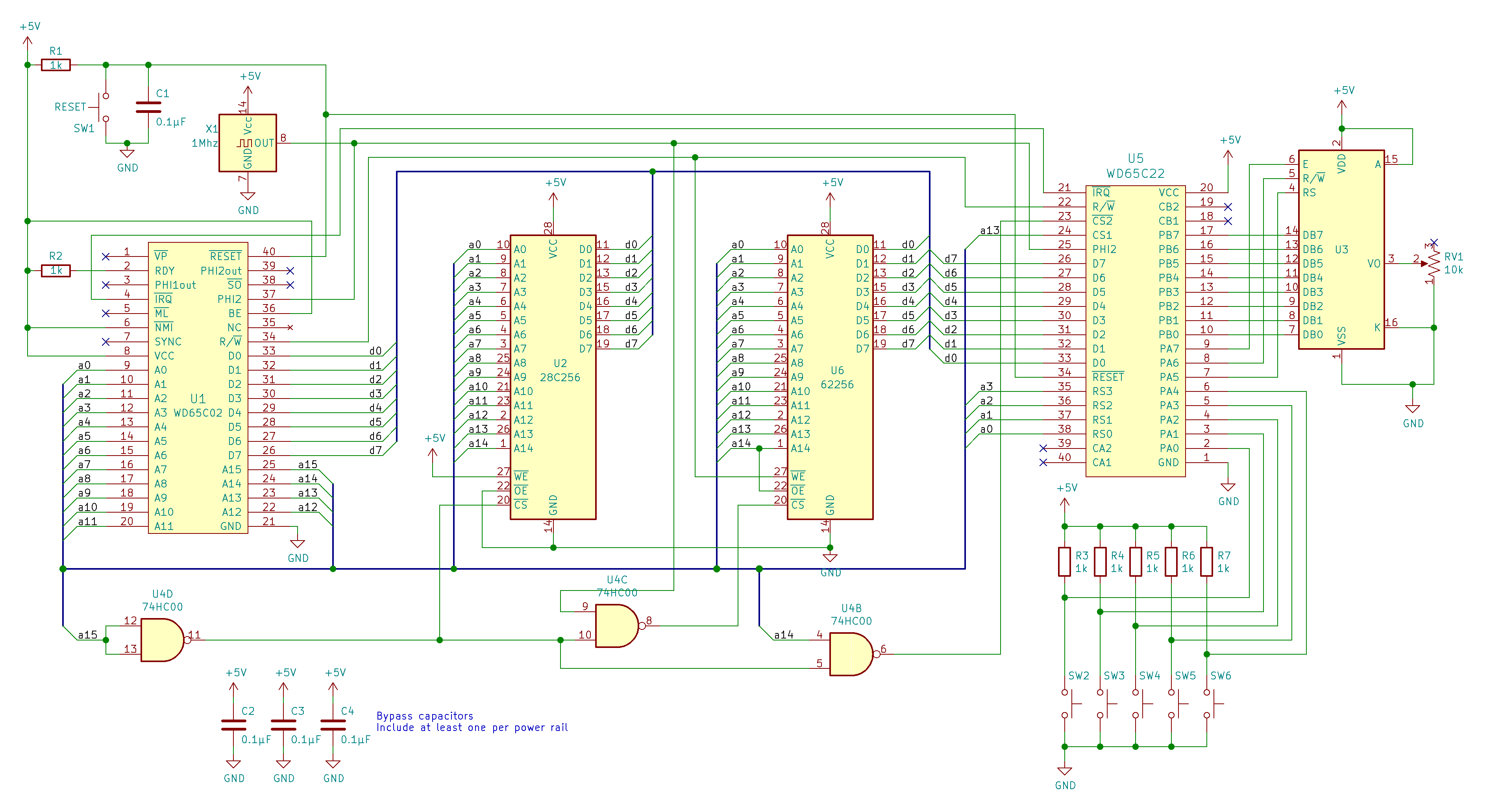
I did look several of these over and you almost see an idiomatic way of connecting things. The schematic below has more of this done correctly.
so I am going with 32K RAM from 0000-7FFF, 8K ROM to upper block E000 (for EEPROM, lolz) through FFFF, this will maintain all vectors. This leaves "8K" open to use for I/O and any screen mapping, about 8K. I could just about leave the controller inputs, at 0000 or whatever, as it will just 'be on the data lines' if I send I bit to it on the 74573, its just an 'enable pin', the other pin Id probably just wire static.
So, I have looked at several schemes:
http://wilsonminesco.com/6502primer/potpourri.html
https://eater.net/schematics/6502.png
https://preview.redd.it/olj13ery7f841.j ... 03c67ae822
https://preview.redd.it/levfg7dz9f841.j ... 49f3efdca4
https://preview.redd.it/lrfnm9259f841.j ... 2259307b70
there seems to be an idiomatic way of doing things, I can probably get away with not using a VIA, though it has a LOT going for it.
If my RAM does not use A15, then I want it's CS or Enable to be inverted from this one pin, this is the fastest way to start Chip Select, as with 1 bit, upper and low address space is on or off, so, A15 is a 'Primary' control line.
When A15 is on (need to get more used to and familiar with high or low), then 'all the other stuff is on' and RAM is 'off'.
Next is ROM, and uses A0-11 (12 bit, 8k) and does not use A14 or A13, so there are two other control lines. I wont need a Write Enable on the ROM for this, it will be held 'off/no write'. so ROM needs few lines. Next is display and it needs a couple of control lines and the data buss for commands and data with 8k internal RAM you can read from, though I have no intention to. it will mostly just be a single address you send to over and over again, it doesnt map its RAM to the address buss, it just serves whatever you request several cycles later back to the data buss. and then the buttons just go 'wherever' because its only going to be a gate with an Output Enable bit to expose it to the Data buss.
So, that would map fairly idiomatically to a 7400 NAND arrangement.
A15 is CS RAM/Other
A14/A13/A12 is free if A15 is on.
A14 = ROM
A13 = Display
A12 = Buttons
I very much think there is a way here to use an inverting transistor (which can take the place of a wire in this cramped space with its leads) instead of a full NAND... if there were a way to use the 6502 pins as a CS line... or such, basically any other control line of some type, OE, CS, etc...
I didnt see one though.
I am highly interested in adding a 6522, it complicates and simplifies things. It seems like any Address Pins lost to it are recovered with CA1/2 and CB1/2, plus the Ports, and the internal registers and functions. If I can run without it I will, though I wonder if I can use a 6522 without a 7400... if so, the 74573 is 20 pins and a 7400 NAND is 14 and so totally justified. On future designs (I found a nice standard enclosure on mouser/digi for about $10) I will use on future builds) having a GPU, a VIA and a USB or DB-9 will be standard, probably an SD card or similar.
for now though, its just a mint can and a 6522 is cool yet extra right now. I ordered one, Ill see if it fits, between a sound chip, the 74573 gate, and any other logic, its a good thing. I could put the display on Port A and the controls and sound and I/O and timers and such on Port B. I almost think it will work. Once you print a board, its no problem, with this perfboard, I dont want it if I can help it. a noise diode turned on and off makes drum sounds...
gotta think like that..
okay, so I think I can get some control lines, I can tie a lot of pins high or low, and it seems RAM is tied to the clock a lot, this is for WRITE operations?
the RAM leaves pin 15 open, when its on, ROM doesnt use 14 or 13, and if the display isnt using those, then pin 12 can OE the 74573 to put the 8 buttons on the data bus to whatever register (Acc)
this does need a 7400 or some other setup then. if I could use the SO, SYNC, BE or MLB pins, I think that might simplify a few things, though they do not seem to be very useful as is.
anyway, I see why the 7400 is so idiomatic, and get the gist of how to set this up. and still not need a 6522 yet, even though it might be a good idea.
if the 6522 could automate block transfers to the display, or otherwise 'do much without needing as much work without it' Id use it for sure.
I could get a 6522, and replace the 74573 with an audio chip, usb or support circuity maybe... lotta wires though in a can... idk, Ill see if it fits. be cool if it does, would run the display with CA1/CA2 to the video chip selects I guess... so much extra wires, so easy on a PCB with PLCC sockets, lol
Proxy wrote:
i mean a VIA would make connecting some buttons pretty easy
Quote:
but since you want to use discrete logic, you can do it like the NES. which only latches the controller inputs when the CPU wants to read them. though the NES controller used a shift register because it send the data over a serial line. in your case all buttons are directly on the PCB so you could get away without a latch and just use a simple tri-state buffer (and maybe some debouncing circuitry). the buffer would be enabled whenever the CPU reads from a specific address, which depends on how your logic is built.
Just using a simple Latch/Buffer is probably ok., yet it has its own challenges. I have a choice of several chips. the 74573 is pretty simple as a 'gate', its just a single pin and the 'data side' goes to the 6502.. I think this might be easy to wire up maybe...
Ultimately, yes, just like an NES controller, this device has only 8 input buttons, mapped to a specific address in RAM, one bit for each button, up.down.left.right.red.blue.yellow.green. I will discuss use of a VIA below.
cjs wrote:
wayfarer wrote:
what I am after is when a button is pressed, it latches to an input. polled by the CPU every so often and clears the buffer. ...
Quote:
It will probably easier not to have the buttons latch when they are pressed but instead just let their state be their state, whatever it is when you scan them. (... None of the systems I've examined do any debouncing at all, so it seems that as long as you're scanning the buttons frequently enough, but not too frequently, everything there is fine. ...
Quote:
If you want to study some hardware and code that uses this technique, ...
cjs wrote:
i'd recommend putting all your IO in roughly the same area, for example 256 bytes directly at the start of your ROM (let's say $C000-$C0FF). that would mean your decoding logic checks if the upper 8 bits of the address bus are equal to $C0, and if true generate a single "IO Enable" signal which you can use with the lower 8 bits of the address bus to see which IO decide specifically is being addressed. that way you decode IO Addresses in 2 steps, with the upper 8 bits taken care of by a single comparator, so you only need to worry about the bottom 8 bits per IO device, which makes the logic a bit easier if you have multiple IO devices. (at the expense of some propagation delay)
at least that's how i do it on my SBCs!
Quote:
On a side note, with RAM it doesn't matter how you order the address or data lines when connecting to the CPU, it will still work perfectly fine. so for those you can map the lines however it fits best with your routing.
so here it seems I can or should do that, though exactly how was not lining up as expected. the design below is much cleaner.
Address Decoding: latches and buffers and gates oh my!
Quote:
Quote:
so, if I have an 8-bit latch tied to a set of 8 buttons, how do i make that byte... $FFF1-FFF2 or whatever that is available to the CPU to read?
Quote:
I would start with Address Decoding from the Wilson Mines 6502 primer. Once you've digested that, I cannot strongly enough recommend examining and understanding the address decoding on some existing systems such as Grant's 7-chip 6502 computer, ...perhaps including a commercial computer or two ...
Quote:
I suspect the simplest system will be to reduce your ROM to 16K and have your display at $8000-$9FFF and buttons at $A000-$BFFF. (Or if you need more ROM and less RAM, reduce RAM to 16K and put your display at $4000-$5FFF and buttons at $6000-$7FFF.) Design this out to get a sense of how it works. If you want to get much more complex than that, you'll probably start to see why people like to use PLAs, CPLDs or microcontrollers emulating devices for this sort of thing.
So, I have looked at several schemes:
http://wilsonminesco.com/6502primer/potpourri.html
https://eater.net/schematics/6502.png
https://preview.redd.it/olj13ery7f841.j ... 03c67ae822
https://preview.redd.it/levfg7dz9f841.j ... 49f3efdca4
https://preview.redd.it/lrfnm9259f841.j ... 2259307b70
there seems to be an idiomatic way of doing things, I can probably get away with not using a VIA, though it has a LOT going for it.
If my RAM does not use A15, then I want it's CS or Enable to be inverted from this one pin, this is the fastest way to start Chip Select, as with 1 bit, upper and low address space is on or off, so, A15 is a 'Primary' control line.
When A15 is on (need to get more used to and familiar with high or low), then 'all the other stuff is on' and RAM is 'off'.
Next is ROM, and uses A0-11 (12 bit, 8k) and does not use A14 or A13, so there are two other control lines. I wont need a Write Enable on the ROM for this, it will be held 'off/no write'. so ROM needs few lines. Next is display and it needs a couple of control lines and the data buss for commands and data with 8k internal RAM you can read from, though I have no intention to. it will mostly just be a single address you send to over and over again, it doesnt map its RAM to the address buss, it just serves whatever you request several cycles later back to the data buss. and then the buttons just go 'wherever' because its only going to be a gate with an Output Enable bit to expose it to the Data buss.
So, that would map fairly idiomatically to a 7400 NAND arrangement.
A15 is CS RAM/Other
A14/A13/A12 is free if A15 is on.
A14 = ROM
A13 = Display
A12 = Buttons
I very much think there is a way here to use an inverting transistor (which can take the place of a wire in this cramped space with its leads) instead of a full NAND... if there were a way to use the 6502 pins as a CS line... or such, basically any other control line of some type, OE, CS, etc...
I didnt see one though.
I am highly interested in adding a 6522, it complicates and simplifies things. It seems like any Address Pins lost to it are recovered with CA1/2 and CB1/2, plus the Ports, and the internal registers and functions. If I can run without it I will, though I wonder if I can use a 6522 without a 7400... if so, the 74573 is 20 pins and a 7400 NAND is 14 and so totally justified. On future designs (I found a nice standard enclosure on mouser/digi for about $10) I will use on future builds) having a GPU, a VIA and a USB or DB-9 will be standard, probably an SD card or similar.
for now though, its just a mint can and a 6522 is cool yet extra right now. I ordered one, Ill see if it fits, between a sound chip, the 74573 gate, and any other logic, its a good thing. I could put the display on Port A and the controls and sound and I/O and timers and such on Port B. I almost think it will work. Once you print a board, its no problem, with this perfboard, I dont want it if I can help it. a noise diode turned on and off makes drum sounds...
gotta think like that..
okay, so I think I can get some control lines, I can tie a lot of pins high or low, and it seems RAM is tied to the clock a lot, this is for WRITE operations?
the RAM leaves pin 15 open, when its on, ROM doesnt use 14 or 13, and if the display isnt using those, then pin 12 can OE the 74573 to put the 8 buttons on the data bus to whatever register (Acc)
this does need a 7400 or some other setup then. if I could use the SO, SYNC, BE or MLB pins, I think that might simplify a few things, though they do not seem to be very useful as is.
anyway, I see why the 7400 is so idiomatic, and get the gist of how to set this up. and still not need a 6522 yet, even though it might be a good idea.
if the 6522 could automate block transfers to the display, or otherwise 'do much without needing as much work without it' Id use it for sure.
I could get a 6522, and replace the 74573 with an audio chip, usb or support circuity maybe... lotta wires though in a can... idk, Ill see if it fits. be cool if it does, would run the display with CA1/CA2 to the video chip selects I guess... so much extra wires, so easy on a PCB with PLCC sockets, lol
Re: Tinker, 6502 in a can.
(Note: this is rather long and I was too tired to properly proofread it by the time I was done, so there may be errors or unclear things I didn't catch.)
Controller Mapping
This is roughly the way keyboard scanning works on many '70s and '80s 8...gotcha, I am not putting a full keyboard on here...This is to keep it simple and minimize complexity and hardware connections.
It doesn't matter; your buttons are exactly the same thing as one row of a keyboard: it's a keyboard with a single row. If you think of a keyboard as different from your buttons (beyond the row enables) it's worth studying more closely how keyboard scanning works until you see that it's just a one-row keyboard.
So the trouble here is 'missing' an input because of operator timing...
It's not an issue so long as you're scanning reasonably often, as you've seen when you used a keyboard on a TRS-80, PET, C64, MSX or many other old computers. If you scan 60 times per second you're guaranteed to see any key that's held down for at least 16.6 ms, which is faster than a human presses and releases a key. You'll note that the NES controller, too, uses a CD4021B shift register which does not latch when a button is pressed, but latches only when the NES main unit strobes the clock signal. So there, too, in theory, if a button is not held down for long enough it will be missed.
The '573 won't do what you seem to be saying you want (latch each individual button on a button press) anyway, since it has only one latch input. To latch on a button press you need an individual flip-flip or latch for each input, set up as a bistable multivibrator that can be reset by the CPU after it's triggered. You could build something like this, but it's a bunch of extra devices, extra wiring, extra work for the code running on the CPU, and just isn't necessary as we saw above.
(And note that the software will still have to track both down and up states; if you unlatch the input it will immediately latch again if the button is still held down, so doing a "scan; see latched; unlatched; scan; see latched" sequence does not mean the button has been pushed twice.)
Right. Basically, you have the address decoding assert /OE (bring it low) when the CPU wants to read it, and deassert /OE (bring it high) when the CPU is accessing anything else. You can just wire LE/Load high so that it's always showing on its outputs (when /OE is asserted) the current state of the buttons. (Note that bringing LE low will capture the current state of all the buttons at once; but you're doing that anyway at the moment you read from it with LE high, anyway.)
But one thing you're missing there is that you need a pull-up resistor on every input line of the '573. Closing a switch properly brings its input line to ground, but with the switch open the line will be floating, and so you'll get a random value.
Or you could simply use a PIA, which has internal pull-ups in the chip so you don't need another eight external resistors. :-) (Check the data sheet for the particular one you're using, though. I just noticed in that in the Ben Eater schematic you linked, he's got external pull-up resistors on his switches even though he's using Port A of the 6522. From a look at the data sheet, it appears that, unlike the Motorola 6820, the MOS 6522 does not have internal pullups.)
On a future project yes, this is such a deep dive for this, its beyond the scope of an altoids can.
Well, to me it seems not, given the difficulty you're currently having with seeing how it's basically just what you want to do. Again, if you ignore the row selection and treat your system as a keyboard with just one row, all the rest of what you learn from the "deep dive" is exactly what you need for this.
Address Decoding
No, of course not. The whole point of address decoding circuitry is to generate the chip select signals. The CPU has no idea what it's accessing when it puts an address on the address bus; it's up to the address decoding circuitry to look at that address (and perhaps other state) and enable the correct device. (The same address might even cause different devices to be enabled at different times; this is how bank switching works.)
With 32K RAM and 8K ROM, you have 24K remaining for I/O. I'm not sure what you mean by "screen mapping"; the display you've chosen is just another I/O device. If you're thinking of having a frame buffer, where you have separate code that reads that area of memory and updates the screen to match it, that frame buffer would be in RAM. (It's sort of a "soft" frame buffer, really, since it would be code reading it rather the screen hardware reading the RAM directly as on an TRS-80/PET/Apple II/C64/etc.)
One plan you might consider, since you're good with 32K RAM and ROM and I/O sharing the other 32K, is to use A15 to determine whether you enable RAM or ROM+I/O, and then for the ROM+I/O section use a '138 decoding A14, A13 and A12 to eight blocks of 4K each. You can then use two or four of these to enable 8K or 16K of ROM, and each remaining block for one I/O device. (This is exactly how the RC6502 SBC is set up.) And this can be done entirely with the '138 and a '00 quad NAND gate, the latter supplying both the decoding and the clock qualification for the RAM.
just about leave the controller inputs, at 0000 or whatever, as it will just 'be on the data lines' if I send I bit to it on the 74573, its just an 'enable pin', the other pin Id probably just wire static.
Sure, but how do you "send the bit" (i.e., assert /OE) on the '573? You need to design circuitry that does that when it sees a specific address (or range of addresses) on the bus.
I've not done a detailed examination of the other schemes you linked, but they look reasonable. I'd suggest you go through all of those and study them until you know exactly how they work, and can say for any address what combination of outputs those circuits will generate. It's a bit tedious, perhaps, but doing that exercise is how you build an intuition for address decoding systems.
Sure, but do you understand that whether or not you use a VIA (or PIA) is completely irrelevant to those decoding schemes? Whether you are enabling a VIA or enabling a '573, the address decoding is exactly the same.
You're still more than a bit confused here; you should go back to the schematic that you think is doing this and work out what it's really doing. Here are some of the mistakes you made:
Again, you're confused. As I mentioned above, it doesn't matter if you use a 6522 or a '573, you still need an enable line for each, and they're both enabled in the exact same way. No, you can't use a 6522 without a 7400 (or some similar substitute), it won't save you any decoding logic (unless you use it to interface to multiple devices that you would otherwise attach directly to the data bus), and CA1/2, CB1/2 and the Ports have nothing to do with decoding.
Yes. This is called "ϕ2 write qualification" and is discussed in detail in Garth's pages, as well as most 6502 hardware tutorials.
Controller Mapping
wayfarer wrote:
cjs wrote:
wayfarer wrote:
what I am after is when a button is pressed, it latches to an input. polled by the CPU every so often and clears the buffer. ...
Quote:
Quote:
It will probably easier not to have the buttons latch when they are pressed but instead just let their state be their state, whatever it is when you scan them.
The '573 won't do what you seem to be saying you want (latch each individual button on a button press) anyway, since it has only one latch input. To latch on a button press you need an individual flip-flip or latch for each input, set up as a bistable multivibrator that can be reset by the CPU after it's triggered. You could build something like this, but it's a bunch of extra devices, extra wiring, extra work for the code running on the CPU, and just isn't necessary as we saw above.
(And note that the software will still have to track both down and up states; if you unlatch the input it will immediately latch again if the button is still held down, so doing a "scan; see latched; unlatched; scan; see latched" sequence does not mean the button has been pushed twice.)
Quote:
There is a buffer and it actually looks simple and not too bad, its in the picture below, the 74'573. It just needs two control pins, more on that below. It would just 'expose the pins' when told to, so addressing on that just needs to turn everything off and let it be on the data buss...
But one thing you're missing there is that you need a pull-up resistor on every input line of the '573. Closing a switch properly brings its input line to ground, but with the switch open the line will be floating, and so you'll get a random value.
Or you could simply use a PIA, which has internal pull-ups in the chip so you don't need another eight external resistors. :-) (Check the data sheet for the particular one you're using, though. I just noticed in that in the Ben Eater schematic you linked, he's got external pull-up resistors on his switches even though he's using Port A of the 6522. From a look at the data sheet, it appears that, unlike the Motorola 6820, the MOS 6522 does not have internal pullups.)
Quote:
Quote:
If you want to study some hardware and code that uses this technique, ...
Address Decoding
Quote:
yes this is the part I am trying to sort out. The 6502 doesn't have any Chip Select lines.
Quote:
so I am going with 32K RAM from 0000-7FFF, 8K ROM to upper block E000 (for EEPROM, lolz) through FFFF, this will maintain all vectors. This leaves "8K" open to use for I/O and any screen mapping, about 8K.
One plan you might consider, since you're good with 32K RAM and ROM and I/O sharing the other 32K, is to use A15 to determine whether you enable RAM or ROM+I/O, and then for the ROM+I/O section use a '138 decoding A14, A13 and A12 to eight blocks of 4K each. You can then use two or four of these to enable 8K or 16K of ROM, and each remaining block for one I/O device. (This is exactly how the RC6502 SBC is set up.) And this can be done entirely with the '138 and a '00 quad NAND gate, the latter supplying both the decoding and the clock qualification for the RAM.
just about leave the controller inputs, at 0000 or whatever, as it will just 'be on the data lines' if I send I bit to it on the 74573, its just an 'enable pin', the other pin Id probably just wire static.
Sure, but how do you "send the bit" (i.e., assert /OE) on the '573? You need to design circuitry that does that when it sees a specific address (or range of addresses) on the bus.
I've not done a detailed examination of the other schemes you linked, but they look reasonable. I'd suggest you go through all of those and study them until you know exactly how they work, and can say for any address what combination of outputs those circuits will generate. It's a bit tedious, perhaps, but doing that exercise is how you build an intuition for address decoding systems.
Quote:
there seems to be an idiomatic way of doing things, I can probably get away with not using a VIA, though it has a LOT going for it.
Quote:
A15 is CS RAM/Other
A14/A13/A12 is free if A15 is on.
A14 = ROM
A13 = Display
A12 = Buttons
A14/A13/A12 is free if A15 is on.
A14 = ROM
A13 = Display
A12 = Buttons
- A15 is ROM+I/O; /A15 ("not A15") is RAM.
- By consequence of the above, A14,A13,A12 are not "free," but are used for decoding if A15 is high.
- A14 is is not just ROM, it's ROM plus everything else in the upper 32K. A13 and A12 also determine whether you're enabling ROM, Display or Buttons. (You can't enable them all, just one!)
- A13 selects ROM; /A13 is not just display but display+buttons. As with the above, when /A13 is asserted, you need to use A12 to determine which one of the two you're going to enable.
Quote:
I am highly interested in adding a 6522, it complicates and simplifies things. It seems like any Address Pins lost to it are recovered with CA1/2 and CB1/2, plus the Ports, and the internal registers and functions. If I can run without it I will, though I wonder if I can use a 6522 without a 7400...
Quote:
and it seems RAM is tied to the clock a lot, this is for WRITE operations?
Curt J. Sampson - github.com/0cjs
Re: Tinker, 6502 in a can.
cjs wrote:
(Note: this is rather long and I was too tired to properly proofread it by the time I was done, so there may be errors or unclear things I didn't catch.)
Quote:
Controller Mapping
This is roughly the way keyboard scanning works on many '70s and '80s 8...gotcha, I am not putting a full keyboard on here...This is to keep it simple and minimize complexity and hardware connections.
It doesn't matter; your buttons are exactly the same thing as one row of a keyboard: it's a keyboard with a single row. ...
wayfarer wrote:
cjs wrote:
wayfarer wrote:
what I am after is when a button is pressed, it latches to an input. polled by the CPU every so often and clears the buffer. ...
also, just solving the 'get the correct device to put (get) its data on the data buss at the right time' is enough of a problem. for now at least, one thing at a time. as discussed further, I do agree with you about 'just exposing the raw input switches cleanly' is fine, no latch needed or anything fancy.
Quote:
Quote:
Quote:
It will probably easier not to have the buttons latch when they are pressed but instead just let their state be their state, whatever it is when you scan them.
Quote:
The '573 won't do what you seem to be saying you want (latch each individual button on a button press) ...
Quote:
(And note that the software will still have to track both down and up states; if you unlatch the input it will immediately latch again if the button is still held down, so doing a "scan; see latched; unlatched; scan; see latched" sequence does not mean the button has been pushed twice.)
Right. Basically, you have the address decoding assert /OE (bring it low) when the CPU wants to read it, and deassert /OE (bring it high) when the CPU is accessing anything else. You can just wire LE/Load high so that it's always showing on its outputs (when /OE is asserted) the current state of the buttons. (Note that bringing LE low will capture the current state of all the buttons at once; but you're doing that anyway at the moment you read from it with LE high, anyway.)
Quote:
There is a buffer and it actually looks simple and not too bad, its in the picture below, the 74'573. It just needs two control pins, more on that below. It would just 'expose the pins' when told to, so addressing on that just needs to turn everything off and let it be on the data buss...
Quote:
But one thing you're missing there is that you need a pull-up resistor on every input line of the '573. Closing a switch properly brings its input line to ground, but with the switch open the line will be floating, and so you'll get a random value.
Quote:
Or you could simply use a PIA, ....)
On a future project yes, this is such a deep dive for this, its beyond the scope of an altoids can.
Well, to me it seems not, given the difficulty you're currently having with seeing how it's basically just what you want to do. Again, if you ignore the row selection and treat your system as a keyboard with just one row, all the rest of what you learn from the "deep dive" is exactly what you need for this.
Quote:
Quote:
If you want to study some hardware and code that uses this technique, ...
Quote:
Address Decoding
Quote:
yes this is the part I am trying to sort out. The 6502 doesn't have any Chip Select lines.
got it, 6522 needs CS1/CS2 and 4 Register select lines. Plus the general I/O lines, R/W and PHI2
Quote:
Quote:
so I am going with 32K RAM from 0000-7FFF, 8K ROM to upper block E000 (for EEPROM, lolz) through FFFF, this will maintain all vectors. This leaves "8K" open to use for I/O and any screen mapping, about 8K.
Quote:
One plan you might consider, since you're good with 32K RAM and ROM and I/O sharing the other 32K, is to use A15 to determine whether you enable RAM or ROM+I/O, and then for the ROM+I/O section use a '138 decoding A14, A13 and A12 to eight blocks of 4K each. You can then use two or four of these to enable 8K or 16K of ROM, and each remaining block for one I/O device. (This is exactly how the RC6502 SBC is set up.) And this can be done entirely with the '138 and a '00 quad NAND gate, the latter supplying both the decoding and the clock qualification for the RAM.
Quote:
Quote:
I've not done a detailed examination of the other schemes you linked, but they look reasonable. I'd suggest you go through all of those and study them until you know exactly how they work, and can say for any address what combination of outputs those circuits will generate. It's a bit tedious, perhaps, but doing that exercise is how you build an intuition for address decoding systems.
Sure, but do you understand that whether or not you use a VIA (or PIA) is completely irrelevant to those decoding schemes? Whether you are enabling a VIA or enabling a '573, the address decoding is exactly the same.
Quote:
there seems to be an idiomatic way of doing things, I can probably get away with not using a VIA, though it has a LOT going for it.
Quote:
Quote:
A15 is CS RAM/Other
A14/A13/A12 is free if A15 is on.
A14 = ROM
A13 = Display
A12 = Buttons
A14/A13/A12 is free if A15 is on.
A14 = ROM
A13 = Display
A12 = Buttons
- A15 is ROM+I/O; /A15 ("not A15") is RAM.
- By consequence of the above, A14,A13,A12 are not "free," but are used for decoding if A15 is high.
- A14 is is not just ROM, it's ROM plus everything else in the upper 32K. A13 and A12 also determine whether you're enabling ROM, Display or Buttons. (You can't enable them all, just one!)
- A13 selects ROM; /A13 is not just display but display+buttons. As with the above, when /A13 is asserted, you need to use A12 to determine which one of the two you're going to enable.
Quote:
Quote:
I am highly interested in adding a 6522, it complicates and simplifies things. It seems like any Address Pins lost to it are recovered with CA1/2 and CB1/2, plus the Ports, and the internal registers and functions. If I can run without it I will, though I wonder if I can use a 6522 without a 7400...
Quote:
Quote:
and it seems RAM is tied to the clock a lot, this is for WRITE operations?
https://laughtonelectronics.com/Arcana/ ... iming.html
(thats Dr Jeffyl right?)
Re: Tinker, 6502 in a can.
wayfarer wrote:
for sure, I get what you are saying I looked over a few KB and keypad 5x5 decoder circuits a few weeks ago when I was figuring out keys for the Qronos portable jobsite/trail calculator. ...Keyboard encoding and decoding is a problem for another day.
Quote:
indeed, I was aiming for 30 Hz myself, Ill see if that is fast enough in testing.
Quote:
I gotcha, like I said, Im fine with this '573 solution, its simple and will work for now and allow focusing on the real problem, buss decoding and control.
Quote:
For the life of me, I also thought you could use all the WDC extra pins like SO, SYNC MLB and BE to control I/O devices somehow... alas, not quite, though I think one makes DMA easier....
Quote:
got it, 6522 needs CS1/CS2 and 4 Register select lines. Plus the general I/O lines, R/W and PHI2
Quote:
so the display modules all have 8k onboard ram, its just only available at the one address/port so its not really useful, you can read from it....
Think of it like the memory of another computer that you're accessing over a network.
Quote:
I am not sure I need the '138 here, Im pretty sure I can just use a 7400...
Quote:
yeah they all look basically the same, and use a 7400 to encode the upper 4 data lines as chip selects etc. its all 'idiomatic' at this point.
...
we are totally saying the same things from different directions, you are saying 'these use' I am saying 'when not using this, it frees these up'. totally get you.
...
we are totally saying the same things from different directions, you are saying 'these use' I am saying 'when not using this, it frees these up'. totally get you.
Code: Select all
┌──────┬──────────────┬─────────────────────┐
│ │ A14 │ 16K ROM │
│ ├───────┬──────┼─────────────────────┤
│ A15 │ │ A13 │ 8K I/O device 2 │
│ │ /A14 ├──────┼─────────────────────┤
│ │ │ /A13 │ 8K I/O device 1 │
├──────┴───────┴──────┼─────────────────────┤
│ /A15 │ 32K RAM │
└─────────────────────┴─────────────────────┘
It's not like, "one address line selects one thing"; it's a cascading tree of, "one address line selects the next group of stuff, with further selection done by the address lines below it." (This is part of why the '138 makes things simpler; it handles three address lines – eight blocks because 2³=8 – worth of decoding.)
Quote:
If I could put ROM behind the 6522....
Quote:
I never need to be reading ROM and the controller at the same time in the same operation.
Quote:
They could share a port, and then Id use the Cx1/2 handshake bits to control which one was read from.
Quote:
I do not think I can get the 6522 to pass through the ROM on bootup though....
Curt J. Sampson - github.com/0cjs
- GARTHWILSON
- Forum Moderator
- Posts: 8775
- Joined: 30 Aug 2002
- Location: Southern California
- Contact:
Re: Tinker, 6502 in a can.
wayferer, let's see if this helps any. Here's another way of looking at it, assuming you still want 8K of ROM and 16K of RAM (although there's an awful lot to review in the posts above, and I'm not sure I have the latest wish list in mind):
For 8K of ROM, all three high bits must be 1's, and all the remaining 13 bits must be available to the ROM's address inputs. For 32K RAM, although it is selected by having bit 15 low, the remaining address bits must all be available to the RAM's address inputs. Here you'll have a 24K address space for I/O. I think it'd be somewhat better to use the 2nd diagram at http://wilsonminesco.com/6502primer/addr_decoding.html (the address-decoding chapter of the 6502 primer), about 3/4 of the way down the page, which gives 16K of ROM, 32K of RAM, and more I/O devices than you'll ever need. It uses a 74xx00 and 74xx04 (with gates left over for other things).
Every chip needs to be individually addressable for all of its addresses. Duplicated address ranges, and addresses that select more than one thing at a time, are ok as long as you don't use those, and you leave a way to address each chip individually without enabling others, and a way to address each register of each I/O chip individually and each address of each memory chip individually.
For keypad debouncing, I normally go for software debouncing. It can be kind of complex, but sure takes fewer parts. I address this at http://wilsonminesco.com/6502primer/potpourri.html#KBD, after where the bold title at the left margin says, "You must debounce!" Note that as switches wear out, you'll need longer debounce times; so don't go too short and then say, "It works perfectly!", because later it might not. I'm sure everyone here has seen calculators where for example you press the 8 key once and get a whole row of 8's in the display.
On the VIA, D0-D7 go on the processor's data bus, while PA0-7 and PB0-7 and CA1, CA2, CB1, and CB2 go to external things. It's not clear if you understood that. If you put memory out on the VIA's PA/PB/CA/CB pins, it will take multiple processor instructions to read or write each byte. The processor cannot use that memory directly to execute instructions.
Code: Select all
A15 │ A14 │ A13 │ A12...A0 │ used for:
─────┼─────┼─────┼─────────────────┼─────────────
1 │ 1 │ 1 │ --used by ROM-- │ 8K ROM
─────┼─────┼─────┼─────────────────┼─────────────
1 │ 1 │ 0 │ VIAs will │ I/O devices
│ │ │ typically │
1 │ 0 │ 1 │ use A3-A0 │ I/O devices
│ │ │ for register │
1 │ 0 │ 0 │ selects. │ I/O devices
─────┼─────┴─────┴─────────────────┼─────────────
0 │ -------used by RAM------- │ 32K RAM For 8K of ROM, all three high bits must be 1's, and all the remaining 13 bits must be available to the ROM's address inputs. For 32K RAM, although it is selected by having bit 15 low, the remaining address bits must all be available to the RAM's address inputs. Here you'll have a 24K address space for I/O. I think it'd be somewhat better to use the 2nd diagram at http://wilsonminesco.com/6502primer/addr_decoding.html (the address-decoding chapter of the 6502 primer), about 3/4 of the way down the page, which gives 16K of ROM, 32K of RAM, and more I/O devices than you'll ever need. It uses a 74xx00 and 74xx04 (with gates left over for other things).
Every chip needs to be individually addressable for all of its addresses. Duplicated address ranges, and addresses that select more than one thing at a time, are ok as long as you don't use those, and you leave a way to address each chip individually without enabling others, and a way to address each register of each I/O chip individually and each address of each memory chip individually.
For keypad debouncing, I normally go for software debouncing. It can be kind of complex, but sure takes fewer parts. I address this at http://wilsonminesco.com/6502primer/potpourri.html#KBD, after where the bold title at the left margin says, "You must debounce!" Note that as switches wear out, you'll need longer debounce times; so don't go too short and then say, "It works perfectly!", because later it might not. I'm sure everyone here has seen calculators where for example you press the 8 key once and get a whole row of 8's in the display.
On the VIA, D0-D7 go on the processor's data bus, while PA0-7 and PB0-7 and CA1, CA2, CB1, and CB2 go to external things. It's not clear if you understood that. If you put memory out on the VIA's PA/PB/CA/CB pins, it will take multiple processor instructions to read or write each byte. The processor cannot use that memory directly to execute instructions.
http://WilsonMinesCo.com/ lots of 6502 resources
The "second front page" is http://wilsonminesco.com/links.html .
What's an additional VIA among friends, anyhow?
The "second front page" is http://wilsonminesco.com/links.html .
What's an additional VIA among friends, anyhow?
Re: Tinker, 6502 in a can.
@cjs has been really helpful sorting out the addressing methods of the 6502 over on discord!!
thank you much!
Ok, so that's not part of your system RAM at all, then. That's basically sending commands over the I/O ports to the display system to tell it to read or modify its internal RAM, which is not directly accessible to you.
Think of it like the memory of another computer that you're accessing over a network.
that is exactly how I was thinking and it leads into something with ROM as storage like a HDD...
This betrays an essential confusion: you cannot put any memory from which you run a program behind a PIA or similar.as we discussed on discord, this is an advanced technique like Plasmo's Prog65 an MCU injecting code into the the RAM of a running 6502.
Not if you're reading your program code from that ROM.
Well, there are some tricks about doing this kind if thing, such as Plasmo's brilliant Prog65, but seriously, don't even look at that until you understand and get comfortable with basic address decoding, including getting your current project built and working.
yeah this kind of thing is way beyond the scope of this project! 
thank you much!
cjs wrote:
Quote:
so the display modules all have 8k onboard ram, its just only available at the one address/port so its not really useful, you can read from it....
Think of it like the memory of another computer that you're accessing over a network.
Quote:
Quote:
If I could put ROM behind the 6522....
Quote:
Quote:
They could share a port, and then Id use the Cx1/2 handshake bits to control which one was read from.
Quote:
I do not think I can get the 6522 to pass through the ROM on bootup though....
Re: Tinker, 6502 in a can.
I am back at the university this year and got to work on this as part of research credit, we made a few changes to design and overall functionality.
we are looking at using this design and 6502 family hardware in some research projects and for this design to be used by students as part of their coursework, each of them building a 6502 computer and implementing a few experiments.
This is basically the prototype for a another model built after this one, which will be part of an open hardware gaming system 'standard' for 21st century development. Had a great focus group last night with several European and Australian NESDev SIG on discord going over addressing, video, audio and controller interfacing.
One thing at a time, I shall Tinker on.
Re: Tinker, 6502 in a can.
ordered parts at jameco, i already have a breadboard, a nice Twin TI-E41-1060 i got on sale
core of the system:
BREADBOARD POWER SUPPLY,5/3.3V 6-12VIN,5/3.3VOUT,500mA MAX
IC,W65C22S6TPG-14,PDIP-40, VIA,8 BIT I/O PORTS,14MHz
IC,ICL8038CCPD,WAVEFORM GENERATOR,VCO,DIP-14
IC,W65C02S6TPG-14,PDIP-40, MPU,8-BIT,14MHz,65KB MEM
LCD SHIELD,16x2 HD44780 COMPAT WHITE TXT,BLUE BL,FITS ARDUIN (has 5 buttons and reset)
CRY,OSC,HCMOS/TTL,1MHz,200ppm,5V@16mA,5ns,R/F,FULL CAN
IC,EPROM,2764A-25,5V 8kx8,DIP-28,250ns(2764D/2764AF1,2764ADC
IC,SRAM,62256LP-70,5V,32kx8,70ns(52256L-70/62256L-70)DIP-28
input systems
SW DIP,SPST,4-POS,8-PIN LOW PROF,SLIDE RAISED,210-4
SWITCH,DIP,SPST,8-POS,16-PIN,STANDARD PIANO,ROCKER RAISED
NANO CHIP, FOR ARDUINO, CH340
for experiments
IC,74S124N,OSCILLATOR VCO 25-85MHz 15pF SQ WAVE,5V,16-DIP
IC,CD4046,DIP-16, MICROPOWER PHASE LOCK LOOP
they were on sale
@1N6263,@SCHOTTKY DIODE(10) x30
@1N5221B,ZENER,SINGLE,2.4V,500mW,5%,DO-35,2-PIN(10) x100
ADAPTER,PWR PLUG BLK PLASTIC,2.1mm MALE TO 3.5mm MALE
LCD,16x2,WHITE/BLUE,4/8 BIT, BACKLIGHT,W/HEADER
Subtotal: $72.14
ill copy over my parts to first post and start collating datasheets.
At this point, we use almost no extra logic besides the 6502, ram, rom, clock and 6522, which runs sound, video and strobes the controller in the final design, we need like 1 inverter, maybe depending on vendor/config/ram size. This may be done as connecto-components-as-wires out of two transistors in the one place we need it, rather than soldering it 'in plane'.