drogon wrote:
The overflow (V) flag is a somewhat tricky one and often mis-understood.
The flags in general can be quite tricky, but they all have equations you can just run. I don't know if anybody ever specified them for 6502, but Motorola did so in the manual for the 6800. For example, the first part of the
page for ADC is as follows:
Attachment:
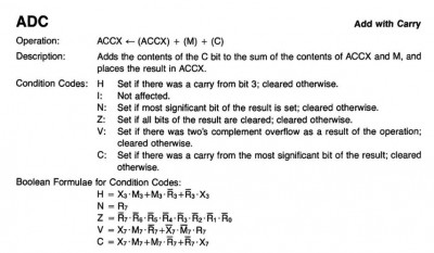 m6800-refman-adc.jpg [ 85.6 KiB | Viewed 2209 times ]
Thus, in
my implementation (in Python), the addition code is as follows. (
m is the "machine," the current state of the CPU.)
Code:
def isneg(b, signbit=7):
sign = b & (1 << signbit)
return 0 != sign
def iszero(b):
return b == 0
def incbyte(byte, addend):
''' Return 8-bit `byte` incremented by `addend` (which may be negative).
This returns an 8-bit unsigned result, wrapping at $FF/$00.
'''
return (byte + addend) & 0xFF
def add(m, augend, addend, carry=0):
''' Return the modular 8-bit sum of adding `addend` (the operand) and
`carry` to `augend` (the contents of the register). Set H, N, Z, V
and C flags based on the result, per pages A-4 (ADC) and A-5 (ADD)
in the PRG.
'''
sum = incbyte(augend, addend)
sum = incbyte(sum, carry)
m.N = isneg(sum)
m.Z = iszero(sum)
bit7 = 0b10000000; bit3 = 0b1000
x7 = bool(augend & bit7); x3 = bool(augend & bit3)
m7 = bool(addend & bit7); m3 = bool(addend & bit3)
r7 = bool(sum & bit7); r3 = bool(sum & bit3)
# The following is copied directly from PRG pages A-4 and A-5.
m.C = x7 and m7 or m7 and not r7 or not r7 and x7
m.H = x3 and m3 or m3 and not r3 or not r3 and x3
m.V = x7 and m7 and not r7 or not x7 and not m7 and r7
return sum
As you can see, I basically just copied the equations straight out of the manual and into my code.
The above is the generic version; implementing the add without carry (
ADD) and with carry (
ADC) versions for each addressing mode is just a line each:
Code:
def adda(m): m.a = add(m, m.a, readbyte(m))
def addaz(m): m.a = add(m, m.a, m.mem[readbyte(m)])
def addam(m): m.a = add(m, m.a, m.mem[readword(m)])
def addax(m): m.a = add(m, m.a, m.mem[readindex(m)])
def addb(m): m.b = add(m, m.b, readbyte(m))
def addbz(m): m.b = add(m, m.b, m.mem[readbyte(m)])
def addbm(m): m.b = add(m, m.b, m.mem[readword(m)])
def addbx(m): m.b = add(m, m.b, m.mem[readindex(m)])
def adca(m): m.a = add(m, m.a, readbyte(m), m.C)
...
That said, because I'm paranoid, I wrote
full test coverage for all instructions anyway. This was actually pretty educational because it forced me to work out every possible case myself, and so gave me a much better understanding of the flags than I'd had before, particularly the V flag. I must admit that this was really more me assuming that the code was correct and tweaking the tests until they matched the code, but I may have found a bug or two in the code by analysing what was going wrong when a test vector didn't produce the results I'd expected. But more often it was because I'd gotten the test vector wrong.
Code:
ADDtests = (
'arg0, arg1, res, H, N, Z, V, C',
(0x00, 0x00, 0x00, 0, 0, 1, 0, 0),
(0x00, 0xFF, 0xFF, 0, 1, 0, 0, 0),
# H: half carry determined by bits 3
(0x0E, 0x01, 0x0F, 0, 0, 0, 0, 0),
(0x0F, 0x01, 0x10, 1, 0, 0, 0, 0),
(0x10, 0x01, 0x11, 0, 0, 0, 0, 0),
# V: overflow determined by bits 6
(0x7E, 0x01, 0x7F, 0, 0, 0, 0, 0),
(0x7F, 0x01, 0x80, 1, 1, 0, 1, 0),
(0x80, 0x01, 0x81, 0, 1, 0, 0, 0),
# C: carry determined by bits 7
(0xFE, 0x01, 0xFF, 0, 1, 0, 0, 0),
(0xFF, 0x01, 0x00, 1, 0, 1, 0, 1),
(0xF0, 0x20, 0x10, 0, 0, 0, 0, 1), # no half carry
# C and V
(0x40, 0xF0, 0x30, 0, 0, 0, 0, 1), # 2's comp: subtract from positive
(0xF0, 0xF0, 0xE0, 0, 1, 0, 0, 1), # 2's comp: subtract from negative
(0x80, 0x80, 0x00, 0, 0, 1, 1, 1),
)
@tc(*ADDtests)
def test_ADD_C0(arg0, arg1, res, H, N, Z, V, C):
runbinary('ADD', arg0, arg1, res, N, Z, V, C, H=H, inflags=R(C=0))
@tc(*ADDtests)
def test_ADD_C1(arg0, arg1, res, H, N, Z, V, C):
runbinary('ADD', arg0, arg1, res, N, Z, V, C, H=H, inflags=R(C=1))
@tc(*ADDtests)
def test_ADC_C0(arg0, arg1, res, H, N, Z, V, C):
runbinary('ADC', arg0, arg1, res, N, Z, V, C, H=H, inflags=R(C=0))
(The
@tc(*ADDtests) bit above just runs the test immediately below it once for each test vector in
ADDtests. There are 14 test vectors in it, so the code above runs a total of 42 unit tests.)


