This is kind of a sad post for the Logisim Project. I've pushed Logisim Evolution beyond what it was intended for and it has gotten to the point where I'm spending more time working around simulation issues than doing design work. I think it's truly amazing what can be achieved in it and it's given me a lot of insight into just how complicated building logic out of discrete circuits is. Ultimately though I've had to end the project because it's too slow, too limited and - as I'm working in my own fork - unusable by anyone else.
My end goal was was to simulate a 'modern' home computer made entirely from discrete ICs with the intent of having something that can be fully understood, built and used by a hobbyist. (It's turned out to be WAY more complex than I thought but still mostly within the realm of reason).
This post isn't just to announce the end of the Logisim Project but also just to give a bit of a view into what I had managed to achieve.
Attachment:
 HCP65.png [ 616.42 KiB | Viewed 8069 times ]
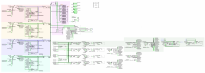
Above is the high level 'motherboard' circuit (somewhat akin to the block diagram BigEd suggested I post ages ago and which I really will... one day).
There are four '816 processes each running with their own private RAM in the four similarly shaped and coloured blocks on the left hand side. There are also four graphics blitters (basically memory copiers) that run in the same memory 'channel' as the MPU in the block with it.
Main memory in the purple block in the top middle can be accessed in time based 'channels'*. The first '816 or blitter gets 25ns of RAM access time then the second '816 gets 25ns of access time then the third and fourth. For a total of four distinct accesses across 100ns. Each '816 runs at 10MHz and each PHI2 clock signal is offset is by 25ns from the previous.
If the '816 is running in private memory then the blitter on the same channel is free to copy bytes (a single row of pixels in a sprite for example) from main memory into video memory. The blitters understand transparency and are mostly intended for drawing graphics but can be used to copy any block of memory from main or video memory to main or video memory. Each blitter is also run on the same 10MHz clock as the '816 on the same channel and takes 3 cycles to draw 2 pixel. One blitter just isn't enough for decent framerates, that's why there are four

The video board is a pair of flipping frame buffers. It's by far the most complicated circuit I've ever designed but not very interesting in terms of what it does; it's just a palettised RAMDAC.
The devices are each 16 bytes of addressable memory somewhere in the zero'th bank. Any '816 can access any device (although they need to negotiate single access amongst themselves first). I've had to do a bit of clock stretching for device reads as there is no way at all a device could respond within 25ns; I've quartered the clock speed to give a device closer to 350ns to respond. Writes are not clock stretched.
This is a very high level summary of what's been simulated in Logisim and each of the 'components' on the 'motherboard' works in simulation. Unfortunately running whole motherboard immediately starts oscillating so I've never seen the computer actually run.
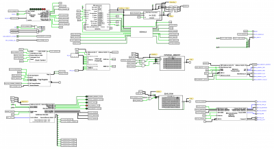
Moving on and drilling down into one of the Microprocessor sub-circuits as an example.
Attachment:
 MPU Kernal Only.png [ 128.86 KiB | Viewed 8069 times ]
This one is probably pretty self-explanatory as it's similar to (and inspired by) lots of previous W65C816 builds.
On this board is an actual microprocessor and 128KB of SRAM that the '816 runs in when in the first 128K addresses.
Clock control is responsible for the mentioned clock stretching, down to 2.5MHz for devices and 5MHz for ROM access. Interrupt Vectoring does what it says on the tin. The Flags register contains a latch that holds two bits of information. The first is whether or not the ROM is addressable; the idea being the ROM is copied into RAM and then turned off. The second is 'lock-in' mode, the clock is increased to 20MHz but all address decoding is disabled allow only the 128K of private memory to be accessed.
The Selector State takes the incoming clock signals and enables or disables various components on the board based on time into PHI2. The Memory Transceiver allows the address and data busses out to the main memory seen on the 'motherboard' and the Device Gateway does the same for devices.
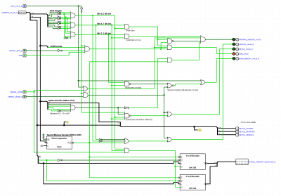
Address Decode also does what it says on the tin but it's composed of the most discrete ICs out of any of the sub-circuits on this board. And as someone asked: "How much decoding is too much address decoding" I think I can answer that

Attachment:
 Address Decode.png [ 64.24 KiB | Viewed 8069 times ]
I'm not going to describe it - there's been enough of that in this post already. I'm just using it as an example of what I did manage in Logisim now that we've finally drilled down to a sub-circuit that's composed only of discrete components.
So that's it. I've learned a lot on my Logisim journey. I like to think I've achieved quite a lot too but that isn't very useful to anyone else in the community

However I'm a crazy bastard and so whilst the Logisim Project is ended the journey doesn't stop here! Soon** there will be a better more stable simulator but that's a post for another time.
* I need a better word than channel but I can't think of anything.** Soon may be subject to unforeseen temporal fluctuations.


