Data flow tracking in various forms is quite common for software these days. Seeing the awesome visual6502 data I wondered "is it possible to do data flow tracking on a transistor level, and get sensible output on a per-instruction level?".
I started out with perfect6502 simulator and added tag bits to nodes, as well as propagation rules. "paint" is added to the values on the data bus, and their (potential) impact is followed throughout the chip. When writing to memory, the tag value is read from the data bus and checked. I needed to toy around with the propagation rules for a while before it was effective, but it looks like the answer is "yes."
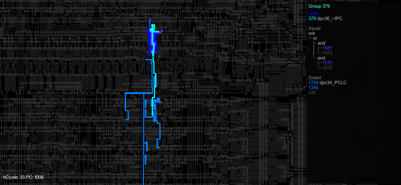
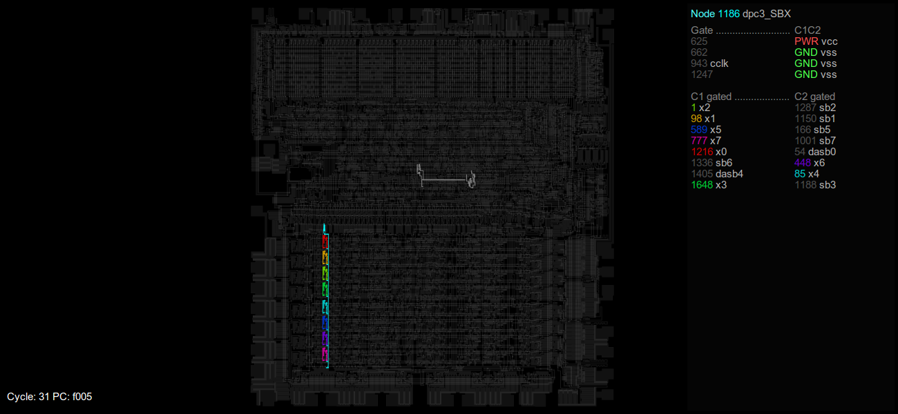
In the animation you can see the data being read, moved from A to X, A being cleared, then X being written back. Then, X is cleared to get rid of the tagging. The same then is repeated for register Y. At the point the data is written back, the data bus is correctly tagged. Being able to follow where values go is useful to learn how the chip works, although of course in the case of 6502 there isn't terribly much left to figure out, but it's still fun.
The colors signify the various tag bits, a generic grey is shown if multiple tags mix in one node.
This is the test program used:
Code:
/* test: ldx */
memory[0xf000] = 0xa5; /* LDA 0x10 */
memory[0xf001] = 0x10;
memory[0xf002] = 0xaa; /* TAX */
memory[0xf003] = 0xa9; /* LDA #0x00 */
memory[0xf004] = 0x00;
memory[0xf005] = 0x86; /* STX 0x11 */
memory[0xf006] = 0x11;
memory[0xf007] = 0xa2; /* LDX #0x00 */
memory[0xf008] = 0x00;
memory[0xf009] = 0x86; /* STX 0x12 */
memory[0xf00a] = 0x12;
/* test: ldy */
memory[0xf00b] = 0xa5; /* LDA 0x10 */
memory[0xf00c] = 0x10;
memory[0xf00d] = 0xa8; /* TAY */
memory[0xf00e] = 0xa9; /* LDA #0x00 */
memory[0xf00f] = 0x00;
memory[0xf010] = 0x84; /* STY 0x11 */
memory[0xf011] = 0x11;
memory[0xf012] = 0xa0; /* LDY #0x00 */
memory[0xf013] = 0x00;
memory[0xf014] = 0x84; /* STY 0x12 */
memory[0xf015] = 0x12;
/* exit sequence token */
memory[0xf016] = 0xa9; /* LDA #0xaa */
memory[0xf017] = 0xaa;
memory[0xf018] = 0x85; /* STA 0xff */
memory[0xf019] = 0xff;
memory[0xf01a] = 0x02; /* HLT */
Address 0x10 in the zero page was marked; so on reading that address, the data bus is tagged
Code:
if(addr == (0x10)) // zero page test
{
setNodeWithTag(state, db0, (data>>0) & 1, 1);
setNodeWithTag(state, db1, (data>>1) & 1, 2);
setNodeWithTag(state, db2, (data>>2) & 1, 4);
setNodeWithTag(state, db3, (data>>3) & 1, 8);
setNodeWithTag(state, db4, (data>>4) & 1, 16);
setNodeWithTag(state, db5, (data>>5) & 1, 32);
setNodeWithTag(state, db6, (data>>6) & 1, 64);
setNodeWithTag(state, db7, (data>>7) & 1, 128);
}
The tag (OR of data bus tags) is logged when writing back to memory:
Code:
Write address 0011: tag 000000ff
Data bus input succesfully tracked to X register.
It is also interesting to see what happens when an opcode (at 0xf000) is tagged instead of a data word,
My plan is to try this next with complex operations involving multiple operands. If there is interest in this I'll publish the code after I've cleaned it up.
("Cycle" in the images is actually half-cycle)
Edit: code for the visualization tool has been published here:
https://github.com/laanwj/xray6502