6502.org Forum  Projects  Code  Documents  Tools  Forum
It is currently Sun Oct 06, 2024 6:30 am

All times are UTC


Forum locked This topic is locked, you cannot edit posts or make further replies.  [ 55 posts ]  Go to page Previous  1, 2, 3, 4  Next
Author Message
 Post subject: [85.23] Tip of the day
PostPosted: Sat Jan 06, 2001 4:15 am 
Offline
User avatar

Joined: Fri Aug 30, 2002 1:09 am
Posts: 8521
Location: Southern California
Tip of the day, #22

RAM needs Φ2 brought into the chip-select logic to avoid invalid writes.  Neither Φ2 nor R/W need to be brought into the chip-select logic for ROM in a 6502 system, but a 65816 system may not latch the correct bank number if ROM output is not disabled when Φ2 is low.  Φ2 must not be brought into the chip-select logic for I/O ICs that have their own Φ2 input, like the 6522 and 6551.

If your RAM were slow enough to need more time (which is unlikely, since SRAM comes in faster speeds than anything else you'll put on your board), you can apply the Φ2 signal to the WE\ and OE\ signals instead.  This will prevent writes to unintended addresses, and prevent possible bus contention, yet still give the RAM more time to respond to its CS\ input if needed.

_________________
http://WilsonMinesCo.com/ lots of 6502 resources
The "second front page" is http://wilsonminesco.com/links.html .
What's an additional VIA among friends, anyhow?


Last edited by GARTHWILSON on Wed Feb 22, 2012 8:46 am, edited 1 time in total.

Report this post
Top
 Profile  
Reply with quote  
 Post subject: [85.24] Tip of the day
PostPosted: Mon Jan 08, 2001 5:32 am 
Offline
User avatar

Joined: Fri Aug 30, 2002 1:09 am
Posts: 8521
Location: Southern California
Tip of the day, #23

You can get RAM, ROM, and plenty of 65xx I/O in your 6502 sytem using a single quad 2-input NAND gate 14-pin IC. Here's one way to do it:

Use one NAND to invert A15, the high address bit, to get A15\. Connect A15\ to the CS\ and OE\ of a 27c256 32Kx8 EPROM, giving you ROM from 8000 to FFFF.

Connect A14 to a 62256 32Kx8 SRAM's A14 and OE\ inputs, and use another NAND for the RAM's CS\ input such that

CS\ = NOT(phase_2 AND A15\). This way you use half the 32Kx8 RAM (16KB), from 0000 to 3FFF.

Connect a third NAND's inputs to A14 and A15\ (derived above), and its output to the CS\ inputs of up to ten I/O ICs like the 6522 and 6551 in the 4000-7FFF range. Individual CS inputs of the various ICs can then go to individual address lines A4,A5,...A13. (The 6522's need A0 to A3 for register selects.)

This scheme is more-or-less what I have on my workbench computer with 3 65c22's and 3 65c51's. Four more could be accomodated without any more glue logic. A tradeoff for the simplicity is that some address ranges in the 16K I/O area duplicate others and thus are essentially unusable; but it fits the purpose nicely.

Image

For more simple address-decoding schemes, see the address-decode section of my 6502 primer. (Actually, you will find the above to be more clear there too.) There is also a basic 6502 computer schematic showing the simple address decoding at http://wilsonminesco.com/6502primer/pot ... ml#BAS_CPU .

_________________
http://WilsonMinesCo.com/ lots of 6502 resources
The "second front page" is http://wilsonminesco.com/links.html .
What's an additional VIA among friends, anyhow?


Report this post
Top
 Profile  
Reply with quote  
 Post subject: [85.25] Tip of the day
PostPosted: Tue Jan 09, 2001 4:22 am 
Offline
User avatar

Joined: Fri Aug 30, 2002 1:09 am
Posts: 8521
Location: Southern California
Tip of the day, #24

An asymmetrical clock may keep your 6502 system from running as fast as it otherwise could. Connecting a crystal or RC directly to the pins of most 65c02's works for non-critical applications; but to improve the timing margins for higher speeds, use an external clock oscillator running at twice the final speed, and use one flip-flop in a 74HC74 or 74AC74 to divide the frequency by two, making the waveform symmetrical in the process. Connect the Q\ output back to the D input, and the oscillator to the flip-flop's clock input. The flip-flop's Q output becomes your new clock source. Here's the connection:

Image

There's more about clock generation in the chapter by that name in the 6502 primer, at http://wilsonminesco.com/6502primer/ClkGen.html .

_________________
http://WilsonMinesCo.com/ lots of 6502 resources
The "second front page" is http://wilsonminesco.com/links.html .
What's an additional VIA among friends, anyhow?


Report this post
Top
 Profile  
Reply with quote  
 Post subject: [85.26] Tip of the day
PostPosted: Wed Jan 10, 2001 4:01 am 
Offline
User avatar

Joined: Fri Aug 30, 2002 1:09 am
Posts: 8521
Location: Southern California
Tip of the day, #25

For easy, compact mass storage, use flash memory with a single power supply voltage and a serial interface. Two large ones I know of are the Atmel AT45D161 2Mx8 (which I've used, and was about $15 in Dec '00), and the AT45DB642 8Mx8 (about $40 in Dec '00). 8Mx8 is about as much as 50 Commodore 64 discs held. This one uses a supply voltage of 2.7 to 3.6 volts; but if you run it on a standard 3.3V, it will be fully compatible with your 5V 6502 system without any level-translation parts because it can tolerate 6V input signals and can output at least 3.1V with a 3.3V supply. These serial flash memories only need four wires for interfacing: clock, serial in, serial out, and chip select. Each additional flash adds one more wire for chip select. There is a write-protect pin for the lowest 128K so you can for example, keep your operating system there so you won't accidentally overwrite it.

Edit, 16 years later: I'm now using the much cheaper 25VF032 4Mx8 SPI flash memory in a tiny SO-8, mounted to tiny PCBs I had made with the SPI-10 interface and am offering for hobbyists. See the front page of my website. There are several other pin-compatible SPI flash ICs that also work on the same tiny board, shown here compared to SD Card and CF card for relative size:

Image

_________________
http://WilsonMinesCo.com/ lots of 6502 resources
The "second front page" is http://wilsonminesco.com/links.html .
What's an additional VIA among friends, anyhow?


Report this post
Top
 Profile  
Reply with quote  
 Post subject: [85.27] Tip of the day
PostPosted: Thu Jan 11, 2001 6:02 am 
Offline
User avatar

Joined: Fri Aug 30, 2002 1:09 am
Posts: 8521
Location: Southern California
Tip of the day, #26

If your small computer project needs a keypad, 3 to 5 keys is often enough. I have Up, Down, Yes/Enter/Select/Continue, No/Cancel/Escape/Exit, and Help/Menu/Edit/Special. In the source code, they're called UPKEY, DNKEY, YESKEY, NOKEY, and HLPKEY. Multi-key combinations (as with "shift") would enhance the possibilities. For my workbench computer, text (mostly source code) is entered by RS-232 from the PC; but the keypad allows quick choices while a program is running.

My workbench computer has these buttons on the board itself, but as I gave it commands from the PC on the desk opposite the workbench and turn around toward the workbench to see instant results, there were times that I wanted the keys within reach without having to get up each time; so I also made a remote keypad and added a pin header on the workbench computer to connect it with a long cord, like this:

Image

A small, portable system we did in the late 80's actually used two keys plus a 2-bit gray-code rotary switch to select menu options and even enter text. For text, rotating the knob would run through a list of characters at the cursor position, and the Enter key selected the current character. It was the Dymo label-maker idea, but special-function characters offered insert & delete, backspace, and so on. Pressing Enter and Exit simultaneously was the equivalent of a "help" key. Text entry was kind of slow, but easy for the user to learn. A later product revision used the above 5-key system instead.

_________________
http://WilsonMinesCo.com/ lots of 6502 resources
The "second front page" is http://wilsonminesco.com/links.html .
What's an additional VIA among friends, anyhow?


Last edited by GARTHWILSON on Sat Mar 03, 2012 8:41 am, edited 2 times in total.

Report this post
Top
 Profile  
Reply with quote  
 Post subject: [85.28] Tip of the day
PostPosted: Fri Jan 12, 2001 5:11 am 
Offline
User avatar

Joined: Fri Aug 30, 2002 1:09 am
Posts: 8521
Location: Southern California
Tip of the day, #27

Some of the densest memories may only be available in SOJ or SOIC surface-mount packages. Since there are no wire-wrap sockets for these, solder them to SOJ-to-DIP adapters so you can use a DIP socket in your home-made computer. The adapter is basically a PC board the size of the DIP socket it plugs into. The top has pads to solder the surface-mount IC to, and there are IC pins comming out the bottom. Some of these adapters are much more expensive than others. Mouser carries Aries, which I have found satisfactory at less than 1/4 of the price of equivalent Ironwood parts.

Attachment:
18011.jpg
18011.jpg [ 5.62 KiB | Viewed 11297 times ]

_________________
http://WilsonMinesCo.com/ lots of 6502 resources
The "second front page" is http://wilsonminesco.com/links.html .
What's an additional VIA among friends, anyhow?


Last edited by GARTHWILSON on Wed Feb 22, 2012 8:51 am, edited 1 time in total.

Report this post
Top
 Profile  
Reply with quote  
 Post subject: [85.29] Tip of the day
PostPosted: Sat Jan 13, 2001 5:04 am 
Offline
User avatar

Joined: Fri Aug 30, 2002 1:09 am
Posts: 8521
Location: Southern California
Tip of the day, #28

Following up on tip #27, hand-soldering surface-mount IC's with your regular solder and soldering iron is easy. Tin the DIP adapter pads at both ends of one row (like pins 1 & 14 for a 28-pin IC). Set the IC on the adapter. Using one hand to keep it properly positioned, heat the IC's two end pins with the soldering iron to tack them down using only the solder you already applied. This "tacking" is just to hold the IC in place for the next step. Check the positioning after tacking the first corner, and straighten if necessary before doing the other end.

Radio Shack sells flux in a tube. Squeeze a little right onto the pins down the side that's not tacked. This flux is what turns a nearly impossible job into an easy one. Go down the side of the IC with the soldering iron, applying solder. For J-leaded parts, you may need to make sure the tip touches not only the pins, but also the pads on the adapter. It's ok if the iron touches 2 or more pins at once. After applying the solder, go down the side with the iron again, holding the adapter up such that the excess solder runs onto the iron, eliminating bridges. There is no need to pay individual attention to each pin.

Now do the same thing on the first side (which was only solder-tacked at the ends earlier). When you're done, clean off the flux with solvent. Even the first time you try, the result may look like it was done by machine.

Edit, 15 years later: I do it a little easier now, no longer needing the extra flux or the clean-up afterward. I soldered these SOJ-36's with .050" pitch with just a 1/8" chisel tip that covered three pins at a time, and regular 60/40 solder, and no extra flux. I tell the method at viewtopic.php?p=48875#p48875 .


Image

_________________
http://WilsonMinesCo.com/ lots of 6502 resources
The "second front page" is http://wilsonminesco.com/links.html .
What's an additional VIA among friends, anyhow?


Last edited by GARTHWILSON on Wed Feb 22, 2012 8:52 am, edited 1 time in total.

Report this post
Top
 Profile  
Reply with quote  
 Post subject: [85.30] Tip of the day
PostPosted: Sun Jan 14, 2001 2:43 am 
Offline
User avatar

Joined: Fri Aug 30, 2002 1:09 am
Posts: 8521
Location: Southern California
Tip of the day, #29

Use the MVN instruction on the 65c802, '816, and '265 to quickly fill a block of memory with a particular byte value.  The source and destination blocks will overlap, but move the block up instead of down, by just one byte.  After some set-up overhead, it will take 7 clocks per byte, meaning 10k can be filled in under 8ms at 10MHz.  What you do is put the desired byte value in the first address, and then have MVN do the iterative work of copying the 1st address to the 2nd, then the 2nd to the 3rd, and so on, until it has been copied to all addresses in the specified range.  (This assumes they are all RAM, or at least act like it.)  Interrupts can be serviced during the process.

_________________
http://WilsonMinesCo.com/ lots of 6502 resources
The "second front page" is http://wilsonminesco.com/links.html .
What's an additional VIA among friends, anyhow?


Last edited by GARTHWILSON on Wed Feb 22, 2012 8:53 am, edited 1 time in total.

Report this post
Top
 Profile  
Reply with quote  
 Post subject: [85.31] Tip of the day
PostPosted: Mon Jan 15, 2001 3:23 am 
Offline
User avatar

Joined: Fri Aug 30, 2002 1:09 am
Posts: 8521
Location: Southern California
Tip of the day, #30

Use pin headers of .025" square posts on .100" centers to select various hardware options like clock sources and speeds, interrupt connections of various I/O IC's (NMI\ versus IRQ\), memory map configuration, and other things you may want to change occasionally after your board is made.  Make the selection by plugging the little shorting blocks onto various pairs of adjacent pins, shorting them together.  You've probably seen these on various cards that plug into your PC.  It's more reliable and takes less space than DIP switches.  Finding wire-wrap pin headers is not as easy as finding those made to solder into a PC board, but they are available.  If you get them from Digi-Key, you may have to get the shrouded kind and cut off the shrouds.  I managed to get a good collection of shroudless ones at an electronics swap meet.

_________________
http://WilsonMinesCo.com/ lots of 6502 resources
The "second front page" is http://wilsonminesco.com/links.html .
What's an additional VIA among friends, anyhow?


Report this post
Top
 Profile  
Reply with quote  
 Post subject: [85.32] Tip of the day
PostPosted: Tue Jan 16, 2001 4:01 am 
Offline
User avatar

Joined: Fri Aug 30, 2002 1:09 am
Posts: 8521
Location: Southern California
Tip of the day, #31

For interfacing your home-made computer's I/O to the outside world, it is often practical to use dual-row pin headers (.025" square posts on .100" centers). Female insulation-displacement connectors (IDC's) on ribbon cable plug onto the headers. These are the ones commonly used in PC's for connecting the disc drives. The pin headers fit the .100" perfboard grid, unlike DB-25's. IDC's are quick to connect to ribbon cable, commonly available, and pretty reliable (although not quite as reliable as wires soldered onto connector pins). You don't need to buy the special press to press the ribbon cable onto the IDC. Just use any bench vise. The common IDC sizes are 10, 16, 20, 26, 34, 40, and 50 contacts. Even Radio Shack has DB-9's and -25's that go onto the ribbon cables the same way.


Image Image

Image

_________________
http://WilsonMinesCo.com/ lots of 6502 resources
The "second front page" is http://wilsonminesco.com/links.html .
What's an additional VIA among friends, anyhow?


Last edited by GARTHWILSON on Wed Feb 22, 2012 8:59 am, edited 1 time in total.

Report this post
Top
 Profile  
Reply with quote  
 Post subject: [85.33] Tip of the day
PostPosted: Wed Jan 17, 2001 3:54 am 
Offline
User avatar

Joined: Fri Aug 30, 2002 1:09 am
Posts: 8521
Location: Southern California
Tip of the day, #32

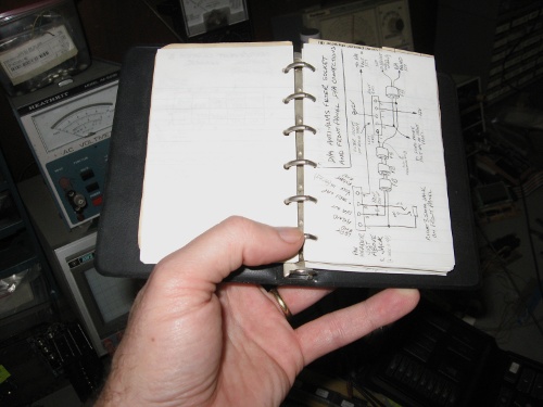
Many projects seen on 6502.org have wires soldered to solder-tail IC sockets. I like certain solder-type breadboards for analog work with all its discrete components; but digital work is almost all IC's, and wire-wrap generally works much better. The tool, tightly wrapping clean wire onto clean posts, makes the corners of the posts bite into the wire, producing a chemical weld. If you unwrap, you can sometimes feel the microscopic welds breaking. Since you don't need to get a soldering iron in between pins, the IC sockets can go right together with no board space between. The shorter wires improve operation with high-speed parts. In my 20 years of using WW, it has proven to be 100.00% reliable. I use the OK Industries WSU 30-M manual wrap tool (the blue one near the top in the picture below). To avoid wire breakage at the end of the insulation, the WSU 30-M wraps a couple of turns of insulated wire first. This insulated part can go over a previous WW since it doesn't need to touch the actual post. This way, you can always get 3 wraps on a 2-level post. Individual turns of bare wire should go against each other with no space between and no overlapping. Practice makes perfect. Do not solder them!

Attachment:
OKIndManualWWtools2.jpg
OKIndManualWWtools2.jpg [ 44.82 KiB | Viewed 6085 times ]


The little blue one near the top is the tool I used to WW my workbench computer whose bottom is shown here:

Image

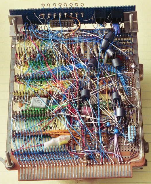
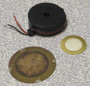
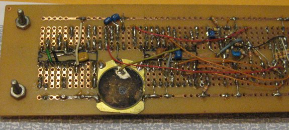
This 4.5 x 6.5" board has 19 ICs plus connectors, keypad, LEDs, DIP headers for discretes, and the piezoelectric beeper, all of which take room. As you can see, you can put parts shoulder to shoulder with no gaps between them, and in most cases, have the wires straight (meaning as short as possible) and without risk of breakage from movement, unlike the situation with soldering wires. Although I've added to it over the years, I used it regularly since originally making it 28+ years ago (as of the time of this edit, Nov 2021), and never had any trouble with it.

The dark-gray drums are ferrite beads put over twisted pairs of wires to reduce unwanted high-frequency digital common-mode signals, forcing them to be differencial. Six of them are in the analog inputs and outputs for the A/D and D/A converters which are very well behaved as a result, in spite of not having a ground plane.

Wire-wrap questions and doubts are answered at http://wilsonminesco.com/6502primer/WireWrap.html .

_________________
http://WilsonMinesCo.com/ lots of 6502 resources
The "second front page" is http://wilsonminesco.com/links.html .
What's an additional VIA among friends, anyhow?


Last edited by GARTHWILSON on Mon Mar 05, 2012 5:59 am, edited 2 times in total.

Report this post
Top
 Profile  
Reply with quote  
 Post subject: [85.34] Tip of the day
PostPosted: Thu Jan 18, 2001 4:45 am 
Offline
User avatar

Joined: Fri Aug 30, 2002 1:09 am
Posts: 8521
Location: Southern California
Tip of the day, #33

The popular intelligent character LCD modules with a parallel interface are inexpensive on the surplus market, and I think you'll find them valuable for your home-made computer project.  The interface is pretty standard except for some pin-out differences and the fact that some need -5V instead of +5V on the viewing angle adjustment pot.  In the power-up routine, you have a choice of a 4- or 8-bit interface method.  There's also E (enable) and RS (register select), bringing the minimum hardware interface requirement to 6 bits.  If you ground the R/W, you will not be able to read data or status from the module, which is ok if you leave enough time to be sure you won't overrun its ability to process the instructions.  The data and RS lines (but not E) can be common to something else like the printer output bits.  The character set includes most of ASCII, but you can also feed it actual bit patterns to make your own custom characters.  It can handle up to 8 special patterns at a time.

See the picture on Tip #40 for a 1x16 intelligent character LCD.

See sample code at http://wilsonminesco.com/6502primer/LCDcode.asm , and connection diagram at http://wilsonminesco.com/6502primer/potpourri.html#LCD .

_________________
http://WilsonMinesCo.com/ lots of 6502 resources
The "second front page" is http://wilsonminesco.com/links.html .
What's an additional VIA among friends, anyhow?


Last edited by GARTHWILSON on Sat Mar 03, 2012 8:53 am, edited 2 times in total.

Report this post
Top
 Profile  
Reply with quote  
 Post subject: [85.35] Tip of the day
PostPosted: Fri Jan 19, 2001 3:00 am 
Offline
User avatar

Joined: Fri Aug 30, 2002 1:09 am
Posts: 8521
Location: Southern California
Tip of the day, #34

Use a pocket-sized loose-leaf ring-type binder for quick-reference information on your computer project. I always keep mine within reach at the workbench to look up I/O connector pin-outs, selectable hardware options, and other hardware info. Two rings seems common for 3x5 cards. Mine has 6 rings and came with 3x5 notebook-type paper. Software documentation is very complete but is all kept in text files on the PC where the text editor's search function can find things quickly, instead of being in the little quick-reference binder.

Image

This one is very full, although it has other modules' info and not just the workbench computer's.

I don't find it necessary, practical, or even helpful to have the whole computer's diagram in a single big sheet. The tiniest I had to draw anything to get it on one of these 3x5" pages was for the PIC programmer which allows setting the Vcc on the PIC for 2V to 6V, and it wasn't hard with a .3mm mechanical pencil.

_________________
http://WilsonMinesCo.com/ lots of 6502 resources
The "second front page" is http://wilsonminesco.com/links.html .
What's an additional VIA among friends, anyhow?


Last edited by GARTHWILSON on Mon Mar 05, 2012 5:12 am, edited 2 times in total.

Report this post
Top
 Profile  
Reply with quote  
 Post subject: [85.36] Tip of the day
PostPosted: Sat Jan 20, 2001 4:45 am 
Offline
User avatar

Joined: Fri Aug 30, 2002 1:09 am
Posts: 8521
Location: Southern California
Tip of the day, #35

Debugging.  Part I.  Hardware.  You can use some very simple tools to debug your new home-made computer without expensive logic analyzers, emulators, simulators, or debuggers.  Starting with a longish routine to actually do something useful will usually disappoint, as it probably won't run the first time and you won't have the means to debug it yet.  Start with a very simple routine to just toggle an output bit, for example.  If the computer doesn't do anything at all, first use your oscilloscope to see if you get a good reset.  (See tip #3.)  Then make sure you have a clean phase 2 toggling at the expected frequency.  (Use the scope probes' x10 setting for all but the lowest frequency work.)  Are address and data lines toggling?  If they sometimes don't go as high or as low as expected, maybe there's bus contention.  If an IC's output voltage never gets very close to power or ground, did you forget to hook one of these up to it?  Is IRQ or NMI going down unexpectedly?  Is the power supply current approximately what you expected?  There's also the single-cycler clock source shown about 3/4 of the way down the clock-generation page of the 6502 primer.  If the hardware seems fine, move on to software.  (to be continued)

_________________
http://WilsonMinesCo.com/ lots of 6502 resources
The "second front page" is http://wilsonminesco.com/links.html .
What's an additional VIA among friends, anyhow?


Last edited by GARTHWILSON on Wed Feb 22, 2012 9:12 am, edited 2 times in total.

Report this post
Top
 Profile  
Reply with quote  
 Post subject: [85.37] Tip of the day
PostPosted: Sun Jan 21, 2001 4:05 am 
Offline
User avatar

Joined: Fri Aug 30, 2002 1:09 am
Posts: 8521
Location: Southern California
Tip of the day, #36

Debugging. Part II. Software. A simple effective debugging tool is a piezoelectric beeper, the kind that's .010"-.020" thick and needs an AC signal in order to sound.

Image

The one at the top is in a black plastic housing that's about 3/8" thick and improves the volume if there's no sounding board. The small one is 3/4" diameter and .012" thick. The bigger one that's tarnished from skin oils and soldering at four points around the edge (but would still work perfectly fine) is 1-3/8" diameter and about .020" thick.

They can be taped or soldered onto the breaboard, so the entire breadboard acts as a sounding board. I've even used scissors to cut them down to fit a tight space, like this one on the back of a mostly analog breadboard with a microcontroller on it:
Image

Very simple beep and delay routines should run on the first try. Write about 3 beep routines of different frequencies and maybe different durations so you can tell them apart. These should save the processor registers like an ISR does. Once these work, call them at appropriate places in your next routine. Put delays between the beeps to make them easier to separate when you hear them. Does it make it to point A before crashing? How about point B? Does the loop that point C is in get run the right number of times? Keep re-assembling and trying your code, each time narrowing down the problem area. LEDs can also be used to monitor the progress; but the software-driven beeper's sound "signature" assures you that the output is not a random effect of a crash. As code development advances, you might incorporate other debugging routines; but in the absence of expensive debugging tools, the lowly beep is indispensable as a "crash-finder".

Without a digital-storage oscilloscope, you can still study a pulse train output by making the software repeat in a loop for an analog scope. For real-time, things that cannot be slowed down to deliver a beep can be watched on the scope with probes on various I/O lines. Sometimes it can be a challenge to get the triggering and sweep rate just right, but it's usually doable. (to be continued)

_________________
http://WilsonMinesCo.com/ lots of 6502 resources
The "second front page" is http://wilsonminesco.com/links.html .
What's an additional VIA among friends, anyhow?


Last edited by GARTHWILSON on Wed Feb 22, 2012 9:11 am, edited 1 time in total.

Report this post
Top
 Profile  
Reply with quote  
Display posts from previous:  Sort by  
Forum locked This topic is locked, you cannot edit posts or make further replies.  [ 55 posts ]  Go to page Previous  1, 2, 3, 4  Next

All times are UTC


Who is online

Users browsing this forum: No registered users and 1 guest


You cannot post new topics in this forum
You cannot reply to topics in this forum
You cannot edit your posts in this forum
You cannot delete your posts in this forum
You cannot post attachments in this forum

Search for:
Jump to: