6502.org Forum  Projects  Code  Documents  Tools  Forum
It is currently Sun Apr 28, 2024 12:40 pm

All times are UTC


Post new topic Reply to topic  [ 23 posts ]  Go to page 1, 2  Next
Author Message
PostPosted: Fri Dec 15, 2023 1:34 pm 
Offline
User avatar

Joined: Wed Feb 14, 2018 2:33 pm
Posts: 1399
Location: Scotland
When I first wrote GIBL (My TinyBasic) I wrote in the README.TXT that it ought to be able to run in a very minimal system having just 4K of ROM and 4K of RAM... (And yes, I know there are more minimal interpreted BASIC/BASIC-like systems out there!)

So... As my winter solstice project (although I'm currently a week ahead of the game as it's not until the 22nd of December this year; 2023) I decided to take up my own challenge... And what better variant of the 6502 to use than the 6507 - as with only 28 pins and just 13 address lines that forces me to stick to 8KB in total and so I split it 4KB ROM and 4KB RAM.

To keep the chip count low, I use a GAL for address decoding and the R/W qualifying and to handle the serial input. There is an 8-bit latch with 4 LEDs and the serial output and decoding for a button input and VIA.

While the 6507 and GAL are proper parts from the 80s the RAM and ROM are more modern parts..

The RAM is a 28-pin static RAM IC (IDT 7164) which actually has 8KB but I'm only using 4KB, tying it's A12 line low.

The ROM is a 28-pin Flash/EEPROM (Atmel 28C256) with 32KB capacity, arranged as 8 "banks" of 4KB. The code resides in the first 4KB bank, the other 7 banks are used for program storage - in a very simple way, filenames are numbers from 1 through 7, but like my SXB version if the first line of the program has a specially crafted REM statement it's used as a filename for the DIR command.

28-pin CPU, 28 pin RAM, ROM, hence "Project-28"...

3 outputs from the 8-bit latch (74ALS573) are used to control the EEPROM bank (A12,13,14), and code to read/write the EEPROM needs to be copied into RAM.

Serial is software at 9600 baud - it could trivially go much faster, but that's good enough for a retro project for now.

There is a 1-bit input button too.

GIBL/TinyBasic supports the LEDs via the LED command and things like

LED=LED+1

works as expected.

And to my surprise it's all working very solidly at 2Mhz on breadboards. I was pleasantly surprised that the 6507 works at 2Mhz too (and I have a few and they're all fine). Their date codes are mid 80's all salvaged from dead Atari 2600s.

Code in the 4K ROM is tight - currently I have just one byte free... Although there is a tiny bit of debug in there, so if I need to tweak something, I have a bit of wiggle room. There is no "monitor" as such - it boots directly into GIBL.

A lot of the spare (from my first GIBL release) space is taken up by the EEPROM read/write codes. I copy a 256 byte page into RAM to do the save/load/chain/dir and auto-start routines.

GIBL uses practically all of page zero - although 16 bytes are used for hardware. There are currently 4 bytes spare in ZP. GIBL doesn't use any RAM outside ZP either - all program variables (@, A...Z), stacks (for/gosub/do and arithmetic evaluation) and other variables are all in ZP.

There is also space for a VIA and that's mapped to the top of page 1.

I've tried to keep it minimal - originally I was going to use the VIA for the bank latch, but decided that might be optional, so am using a separate latch for that plus the LEDs. There is no space in the ROM to add any VIA code, so that will all have to be poked from BASIC, but setting up a timer ought to be possible - although no interrupts here as the 6507 doesn't have any!

There is also no protection against poking garbage into the hardware but that's no different from other systems - see e.g. https://en.wikipedia.org/wiki/Killer_poke

Right now it's all on breadboards but I've just finished up a PCB, so will get it sent off to China today hopefully I'll get them back by the solstice so I can use it to power some LEDs in a festive pattern or something... The PCB is bigger than I had hoped at 100x90mm .

One thing of note - might be handy for others doing software/bit-bang serial... I added an option to disable all output which makes it much easier/faster to upload code into it by copy/paste - So here, typing Ctrl-O toggles output on/off. The issue I was having was that if the system printed a character while being sent a character it would drop the sent character as it can only do one thing at a time, so for quick copy/pastes, Ctrl-O then do the copy/paste thing then Ctrl-O again. It works well.

Code:
;********************************************************************************
;*
;* project-28 memory map:
;*      $00-$EF:        All GIBL data fits here (with a few bytes spare)
;*      $F0             Hardware input. Reads the rxD input pin into D7
;*      $F8             Hardware output: An 8-bit latch:
;*                              Bit 7 is serial Tx
;*                              Bits 6,5,4 are the EEPROM bank select
;*                              Bits 3,2,1,0 are LEDs
;*      $F8             Hardware input: Reads the "button" input into D7.
;*      $0100-$018F     Keyboard input buffer and temp. space for DIR command.
;*      $0190-$01EF     6502 stack - Initialised to $EF.
;*      $01F0-$01FF     Hardware - Reserved for a VIA
;*      $0200-$02FF     Code copied from the ROM into RAM to access the FLASH
;*                              ROM banks as we can only do this from RAM.
;*      $0300-$0FFF     BASIC Program code store and dynamic ram for strings,
;*                              arrays, etc.
;*      $1000-$1FF9     GIBL ROM code.
;*      $1FFA-$1FFF     6507 Vectors - NMI/Reset/IRQ
;*
;********************************************************************************


Attachment:
IMG_20231215_115832_DRO.jpg
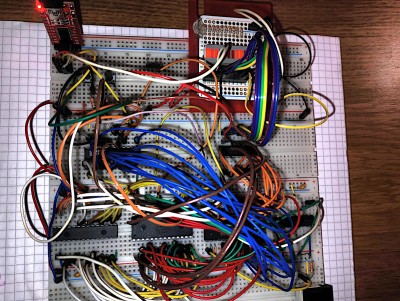
IMG_20231215_115832_DRO.jpg [ 722.27 KiB | Viewed 3599 times ]


I've quite enjoyed the challenge of making a very minimal retro system over the past few weeks and being able to recycle old 6507s as in the past few years I've sort of had the attitude that RAM is cheap, so use it - here I have some very hard constraints to work with...

I have enough bits to make a handful of kits up, (assuming the PCB works!) so if anyone's interested in it let me know and I'll put something together in the new year.

Code:
Project-28
GIBL [v05]

Welcome to GIBL: Gordons Interactive BASIC Language


>LIST
    0 REM!BOOT
   10 PRINT ""
   20 PRINT "Welcome to GIBL: Gordons Interactive BASIC Language"
   30 PRINT ""
   40 END

>DIR
 1: !BOOT
 2:
 3:
 4:  VCCC 2023
 5:  Mandelbrot
 6:  Dumper
 7:  FillerUp

>CH 5
Mandelbrot - Gordons TinyBasic - Integers
Start
......,,,,,,,,,,,,,,,,,,,,,,'''''''''~~~~~=+:*$O:;==~~'''''',,,,,,,,,,,........
.......,,,,,,,,,,,,,,,,,,,,,'''''''''~~~==+%*O  ;;%=~~~~''''',,,,,,,,,.........
........,,,,,,,,,,,,,,,,''''''''~~~'====++:       %++=~~~~'',,,,,,,,,..........
........,,,,,,,,,,,',,,,'''''''~~~=++::+;;*       %;:++===='''',,,,,,..........
.....,,,,,,,,,,,,''''''''~~~~~~~==+; &$%              ;*;$+=~',,,,,,,,,,.......
...,,,,,,,,,,,''''''''''~~~~~~===::;                       +~'''',,,,,,,,,.....
....,,,,,,,,,,,'''~~~=========+++&                       %:==~~''',,,,,,,......
.....,,,,,,''''''~~=+X::+; :+++:;%                        &&=~~''',,,,,,,......
....,,''''''''~~~~=+:%  *O  B*;*%                          $=~~'',,,,,,,,......
,,,,,,''''''~~~~~=++;*X        B                            =~~''',,,,,,,,,,,,.
,,,,,'''~~~~=====;*%&                                      +=~~'',,,,,,,,,,,,,.
,,,,''~~==++++:+*&                                       O:=~~'''''',,,,,,,,,,.
,,,,'                                                   %;+==~~'''',,,,,,,,,,,.
,,,,''~~==++++:+*&                                       O:=~~'''''',,,,,,,,,,.
,,,,,'''~~~~=====;*%&                                      +=~~'',,,,,,,,,,,,,.
,,,,,,''''''~~~~~=++;*X        B                            =~~''',,,,,,,,,,,,.
....,,''''''''~~~~=+:%  *O  B*;*%                          $=~~'',,,,,,,,......
.....,,,,,,''''''~~=+X::+; :+++:;%                        &&=~~''',,,,,,,......
....,,,,,,,,,,,'''~~~=========+++&                       %:==~~''',,,,,,,......
...,,,,,,,,,,,''''''''''~~~~~~===::;                       +~'''',,,,,,,,,.....
.....,,,,,,,,,,,,''''''''~~~~~~~==+; &$%              ;*;$+=~',,,,,,,,,,.......
........,,,,,,,,,,,',,,,'''''''~~~=++::+;;*       %;:++===='''',,,,,,..........
........,,,,,,,,,,,,,,,,''''''''~~~'====++:       %++=~~~~'',,,,,,,,,..........
.......,,,,,,,,,,,,,,,,,,,,,'''''''''~~~==+%*O  ;;%=~~~~''''',,,,,,,,,.........
......,,,,,,,,,,,,,,,,,,,,,,'''''''''~~~~~=+:*$O:;==~~'''''',,,,,,,,,,,........
Finished
Time:     0 secs.

>
>CH 4
   *     *     *
  * *   * *   * *
 *   * *   * *   *
*     *     *     *
 *   * *   * *   *
  * *   * *   * *
   *     *     *
  * *   * *   * *
 *   * *   * *   *
*     *     *     *
 *   * *   * *   *
  * *   * *   * *
   *     *     *
  * *   * *   * *
 *   * *   * *   *
*     *     *     *
 *   * *   * *   *
  * *   * *   * *
   *     *     *


>


Cheers,

-Gordon

_________________
--
Gordon Henderson.
See my Ruby 6502 and 65816 SBC projects here: https://projects.drogon.net/ruby/


Top
 Profile  
Reply with quote  
PostPosted: Fri Dec 15, 2023 2:38 pm 
Offline
User avatar

Joined: Thu Dec 11, 2008 1:28 pm
Posts: 10793
Location: England
A very nice constrained system! I like the control-O idea - simple and effective.


Top
 Profile  
Reply with quote  
PostPosted: Fri Dec 15, 2023 3:06 pm 
Offline

Joined: Fri Jul 09, 2021 10:12 pm
Posts: 741
Very nice indeed, thanks for all the details!

I guess given the CPU doesn't have IRQs, there's kind of no disadvantage to accessing the VIA from BASIC - you can do everything from BASIC that you would have been able to do more natively. The timers will still set the interrupt flags, BASIC can still read them, so it should still be very useful.

Do you have any mockups of what the PCB-based version will look like?


Top
 Profile  
Reply with quote  
PostPosted: Fri Dec 15, 2023 4:38 pm 
Offline
User avatar

Joined: Sun Jun 30, 2013 10:26 pm
Posts: 1927
Location: Sacramento, CA, USA
Very nicely done, Gordon! I envy your productivity. I wish that I could get my rear in gear and catch up on a bewildering array of unfinished projects, some originating deep inside the last century, but inertia is an unforgiving property of nature.

_________________
Got a kilobyte lying fallow in your 65xx's memory map? Sprinkle some VTL02C on it and see how it grows on you!

Mike B. (about me) (learning how to github)


Top
 Profile  
Reply with quote  
PostPosted: Fri Dec 15, 2023 4:44 pm 
Offline
User avatar

Joined: Wed Feb 14, 2018 2:33 pm
Posts: 1399
Location: Scotland
gfoot wrote:
Very nice indeed, thanks for all the details!

I guess given the CPU doesn't have IRQs, there's kind of no disadvantage to accessing the VIA from BASIC - you can do everything from BASIC that you would have been able to do more natively. The timers will still set the interrupt flags, BASIC can still read them, so it should still be very useful.


There is 16-bit peek/poke too, so you ought to be able to kick a timer off and read it with a single (BASIC) instruction but I've not tried that on the VIA yet.

For a timer, you might be able to do something like putting T1 into continuous mode with a suitable count value (say, 20,000 for 100Hz @ 2MHz), then connecting PB7 out to PB6 in and arrange T2 to count pulses then you can read T2. So if T1 is running at 100Hz, then T2 give you a 16-bit 100Hz timer that increments (and rolls over). Good for 10 minutes or so.

And you can chain programs, keeping variables in-tact, so you could have a common one to do the hardware setup then launch your main thing.... Be creative in 3.75KB :-)

Quote:
Do you have any mockups of what the PCB-based version will look like?


I don't (yet) use fancy stuff like KiCAD that can do it for you, but:

Attachment:
project28_pcb.png
project28_pcb.png [ 71.41 KiB | Viewed 3584 times ]


EEPROM and RAM stacked (Thanks to Lee Hart for that idea taken from his VCF 6502 badge - the RAM will be soldered to the board, EEPROM in a socket over it)

Power wise, it's about 180mA @ 5v. I suspect most of that is the 6507 and the GAL though.

It's 100mm wide and 90mm tall - I could have crammed it smaller but it was stating to become a time vs. "I want it before solstice" race...

Cheers,

Gordon

_________________
--
Gordon Henderson.
See my Ruby 6502 and 65816 SBC projects here: https://projects.drogon.net/ruby/


Top
 Profile  
Reply with quote  
PostPosted: Fri Dec 15, 2023 4:47 pm 
Offline
User avatar

Joined: Wed Feb 14, 2018 2:33 pm
Posts: 1399
Location: Scotland
barrym95838 wrote:
Very nicely done, Gordon! I envy your productivity. I wish that I could get my rear in gear and catch up on a bewildering array of unfinished projects, some originating deep inside the last century, but inertia is an unforgiving property of nature.


Thanks, but yes - I have lots of other things to do which I should maybe have been attending to rather than this, however once I get the PCBs and assuming they're OK, then I'll tackle them.

Mostly repairing and sell-on a large quantity of BBC Micros and Apple IIs ... So still 6502 related!

Cheers,

-Gordon

_________________
--
Gordon Henderson.
See my Ruby 6502 and 65816 SBC projects here: https://projects.drogon.net/ruby/


Top
 Profile  
Reply with quote  
PostPosted: Mon Dec 18, 2023 5:54 am 
Offline
User avatar

Joined: Wed Feb 13, 2013 1:38 pm
Posts: 586
Location: Michigan, USA
drogon wrote:
One thing of note - might be handy for others doing software/bit-bang serial... I added an option to disable all output which makes it much easier/faster to upload code into it by copy/paste - So here, typing Ctrl-O toggles output on/off. The issue I was having was that if the system printed a character while being sent a character it would drop the sent character as it can only do one thing at a time, so for quick copy/pastes, Ctrl-O then do the copy/paste thing then Ctrl-O again. It works well.

May I mention how I tackled that problem on my version of Karen Orten's PICL (NIBL) emulator project? I used a single-pin-serial circuit (below) and the TX subroutine simply changes the pin to an output, sends the character, and returns the pin to an input (with pull-up). Terminal is setup with local echo off. Of course this is only really practical if you stick to ASCII characters, like hex files, as opposed to binary transfers.

I'm anxious to see if the final software is flexible enough to be easily used in other hardware configurations. I really enjoyed using NIBL on Karen's SC/MP emulator project.

Take care. Happy Holidays. Mike


Attachments:
single pin serial.png
single pin serial.png [ 14.08 KiB | Viewed 3380 times ]
PICL R2 #2.jpg
PICL R2 #2.jpg [ 184.54 KiB | Viewed 3380 times ]
NIBL Pages.png
NIBL Pages.png [ 46.3 KiB | Viewed 3380 times ]
Top
 Profile  
Reply with quote  
PostPosted: Mon Dec 18, 2023 9:02 am 
Offline
User avatar

Joined: Wed Feb 14, 2018 2:33 pm
Posts: 1399
Location: Scotland
Michael wrote:
drogon wrote:
One thing of note - might be handy for others doing software/bit-bang serial... I added an option to disable all output which makes it much easier/faster to upload code into it by copy/paste - So here, typing Ctrl-O toggles output on/off. The issue I was having was that if the system printed a character while being sent a character it would drop the sent character as it can only do one thing at a time, so for quick copy/pastes, Ctrl-O then do the copy/paste thing then Ctrl-O again. It works well.

May I mention how I tackled that problem on my version of Karen Orten's PICL (NIBL) emulator project? I used a single-pin-serial circuit (below) and the TX subroutine simply changes the pin to an output, sends the character, and returns the pin to an input (with pull-up). Terminal is setup with local echo off. Of course this is only really practical if you stick to ASCII characters, like hex files, as opposed to binary transfers.


Interesting idea - there's no reason it can't work on GIBL (or any other 6502 project that uses bit-banged serial), given the right hardware. The Project-28 board would need to use the VIA for serial to work like this as right now the IO devices are not bi-directional - it's an 8-bit latch for output and 2 pins on a GAL for input and while you can read an output pin from inside the GAL I don't think you can drive it externally.

P-28 was really about a minimal system though - what I could get away with in a traditional ROM/RAM/CPU/IO manner. I think i could do away with the 8-bit latch too if I were to really go to town on the GAL side of things, but I like flashing LEDs...

Quote:
I'm anxious to see if the final software is flexible enough to be easily used in other hardware configurations. I really enjoyed using NIBL on Karen's SC/MP emulator project.

Take care. Happy Holidays. Mike


Thanks.

GIBL is of-course heavily influenced by NIBL (and I own a MK14 so it has a touch of fondness for me too), and so-far I have GIBL working on 4 platforms - my Ruby 816 board where all the IO including a nice read-line routine is handled by the OS (code size 3622 bytes), the 65C134-SXB board - 2 variants, one that runs in RAM that uses the existing monitor code and very little zero page (3691 bytes), and one where I wrote a tiny stub to run in the boot rom to replace the monitor which does serial IO where the code is 3980 bytes (it uses its own getline and print string code and has extra 'filing' code) and the Project-28 board where there is no monitor/os/anything and there the P-28 GIBL code plus serial is currently 4089 bytes, so one byte spare plus 6 for vectors.

The SXB and P28 code also includes save/load/chain/dir code too.

So with a decent monitor - like WozMon or even just external get/put characters then anything's possible.

And... Now you mention it, going back to NIBL it looks like my EEPROM banks in P28 at least are effectively the 4K pages in NIBL, using the chain command rather than page command to link them together.. Variables are preserved but unless you work out whichever page/bank is the largest then TOP will change with each program...

Maybe I ought to get a PICL board or resurrect/expand my old MK14... One day!

Cheers,

-Gordon

_________________
--
Gordon Henderson.
See my Ruby 6502 and 65816 SBC projects here: https://projects.drogon.net/ruby/


Top
 Profile  
Reply with quote  
PostPosted: Mon Dec 18, 2023 12:33 pm 
Offline
User avatar

Joined: Wed Feb 13, 2013 1:38 pm
Posts: 586
Location: Michigan, USA
Well I would love to have GIBL as one of my Apple-1 replica 8K ROM images. Currently I have (1) unaltered WozMon + 4K Integer BASIC + 4K Krusader, and (2) unaltered WozMon + 8K Applesoft Lite. Grant Searle's modified OSI BASIC will also fit in 8K at $E000..$FFFF and I'd also like to add a version of BillO's Tiny Basic (I can easily change the xUART from Apple-1 'PIA' mode to '6551' or '6850 mode).

I've been having a lot of fun finding and running unaltered Apple-1 software.

Cheerful regards, Mike


Attachments:
Crab_Apple_1a.png
Crab_Apple_1a.png [ 844.39 KiB | Viewed 1673 times ]
xUART65 A1 ram-rom.png
xUART65 A1 ram-rom.png [ 160.53 KiB | Viewed 3355 times ]
Startreck session.png
Startreck session.png [ 47.28 KiB | Viewed 3355 times ]
Crab_Apple_1.png
Crab_Apple_1.png [ 60.93 KiB | Viewed 3355 times ]


Last edited by Michael on Tue Jan 09, 2024 4:24 pm, edited 1 time in total.
Top
 Profile  
Reply with quote  
PostPosted: Mon Dec 18, 2023 1:44 pm 
Offline
User avatar

Joined: Wed Feb 14, 2018 2:33 pm
Posts: 1399
Location: Scotland
Michael wrote:
Well I would love to have GIBL as one of my Apple-1 replica 8K ROM images. Currently I have (1) unaltered WozMon + 4K Integer BASIC + 4K Krusader, and (2) unaltered WozMon + 8K Applesoft Lite. I'd also like to add a version of BillO's Tiny Basic (I can easily change the xUART mode from Apple-1 'PIA' to '6551' or '6850).

I've been having a lot of fun finding and running unaltered Apple-1 software.

Cheerful regards, Mike


Getting one of the Apple-1 "clones" is on my to-do list and I have this ... er ....

--- evil laugh followed by an image of a Bond Villain + fluffy white cat on a swivel chair ... "So, Mr 6502, I've been expecting you" --- [*]


... sort of thing about getting GIBL everywhere, however, back in the real world ;-)

Porting it to something with WozMon ought to be fairly easy - it's just the ZP locations that need sorting out although GIBL can use any amount of non-ZP RAM for data, the more you can get into ZP the faster it will run (and smaller the code will be by a few bytes). The P-28 version is probably the ultimate as all data is in ZP with a 16-byte window for hardware - there are then 5 bytes spare... If the monitor could restrict itself to 20 consecutive bytes of ZP either at the top or bottom then it would be easy, however...

My RubyOS version is the smallest as it can call all the OS routines for serial IO, read line, print string and so on and ZP while busy, is well defined and locations $00 through $8F are available for programs to use so 3 stacks have been moved into higher RAM...

The other hurdle will be assembling it outside a cc65/ca65 environment. As each iteration/port has happened I've relied more and more on ca65 features - it would not be hard to use a different assembler but it would take time to understand some of the issues. In particular I'm using the linker config file to specify memory regions and sizes and some program variables (well, just one right now, so I either need to use it for more, or none - hard to know what to do)

There is one other limitation and that's that it needs to fit entirely inside a 4K page. There is a little bit of wiggle room either side but it's all to do with having a 12-bit addressing to call the routines to handle bits of the interpreter from the IL (Intermediate Language) and it's just easier if you can keep it all in the same 4K page.

The putChar code is 39 bytes long and the getChar code is 66 bytes long and they need 3 bytes of ZP (could be just one byte, but 2 are used for the baud which is in-theory changeable from a BASIC program but if you fixed the baud in the code then it's not needed) of-course with a hardware UART/ACIA this code ought to be trivially smaller - to the level of a JSR to a monitor routine, if present, so you can save a lot code there. Also the FLASH save/load/dir code is just under 250 bytes long so if not using that it's a relatively huge amount of space to save along wth the page of RAM it's copied down to... Also things like the LED command - that's another dozen or 2 bytes to save, so plenty of room for other stuff, or not - especially if program save/load is "drop back to the monitor and write a range of bytes to serial in SREC/IHEX/WozMon format, etc." ... (There is a call command!)

For such a relatively small project it seems to have rather a lot of build, etc. requirements...

Anyway, if I have some spare toy money after the festering period I might look at one of the Apple 1 clones or even make myself a Ben Eater thing and port it to that as he's just ported WonMon to it in a fairly authentic way to preserve entry points while using the ACIA.

Or I'll just do something completely different for a while.

Also; Bother. I've just been looking at how hard it might be to turn P-28 into something like your "crab apple" board to run WozMon. Relatively trivial with a 6502 CPU. Hmmm..


Cheers,

-Gordon

[*] Well, the fluffy white cat is actually a white fluffy dog https://unicorn.drogon.net/doodle.jpg who'll lick you to death then demand tummy rubs and my henchwoman side-kick is my night-mare of a horse with the nick-name "The Oncoming Storm", but you get the idea ...

_________________
--
Gordon Henderson.
See my Ruby 6502 and 65816 SBC projects here: https://projects.drogon.net/ruby/


Top
 Profile  
Reply with quote  
PostPosted: Mon Dec 18, 2023 2:14 pm 
Offline

Joined: Fri Jul 09, 2021 10:12 pm
Posts: 741
drogon wrote:
The other hurdle will be assembling it outside a cc65/ca65 environment. As each iteration/port has happened I've relied more and more on ca65 features - it would not be hard to use a different assembler but it would take time to understand some of the issues. In particular I'm using the linker config file to specify memory regions and sizes and some program variables (well, just one right now, so I either need to use it for more, or none - hard to know what to do)

I don't see this as a big issue personally - so long as you can use ca65 to output a binary image, most assemblers will let you then just embed that. Bonus points if you can get sensible label definitions out of ca65 to go with it of course! I think this is what I did for my Fast PDIP system though - I let ca65 do its thing, then made a very small wrapper around it to make it work in my system, more or less a bootstrapper. I did the same thing for the Dormann test suite, which would be very hard to get working in a different assembler than the one it was written for.


Top
 Profile  
Reply with quote  
PostPosted: Mon Dec 18, 2023 2:26 pm 
Offline
User avatar

Joined: Wed Feb 14, 2018 2:33 pm
Posts: 1399
Location: Scotland
gfoot wrote:
drogon wrote:
The other hurdle will be assembling it outside a cc65/ca65 environment. As each iteration/port has happened I've relied more and more on ca65 features - it would not be hard to use a different assembler but it would take time to understand some of the issues. In particular I'm using the linker config file to specify memory regions and sizes and some program variables (well, just one right now, so I either need to use it for more, or none - hard to know what to do)

I don't see this as a big issue personally - so long as you can use ca65 to output a binary image, most assemblers will let you then just embed that. Bonus points if you can get sensible label definitions out of ca65 to go with it of course! I think this is what I did for my Fast PDIP system though - I let ca65 do its thing, then made a very small wrapper around it to make it work in my system, more or less a bootstrapper. I did the same thing for the Dormann test suite, which would be very hard to get working in a different assembler than the one it was written for.


The output of ca65 is a relocatable file. You subsequently need to feed it through the linker to generate an object file at a particular address. The linker reads a config. file to get things like start address and size of segments, pre-defined globals and so on. It also generates a map file with all the symbols and addresses.

So the way I treat is it the same way I've been using assemblers for the past 30+ years. Lots of separate files assembled into .o files then a linker to combine them. Some may say this is overkill but it's how I work and how most people work on e.g. Unix/Linux projects. At least traditionally. cc65 is a C compiler, assembler and linker system that works just like that. I really would not want to put all of GIBL into one big file - I find it more manageable keeping them separate.

It did take me a few minutes to work out how to "fix" the size of a segment, fill it with a data pattern ($FF) and make sure the reset, etc. vectors were in the right place! But once I'd done that it was (for me) a bit of a "duh, of-course that's how it would work" moment.

So that's why porting GIBL may need some cc65/ca65/ld65 experience... It could be done like EhBASIC in one great big file, but I wanted the ease of splitting it all up into separate files to be more manageable.

-Gordon

_________________
--
Gordon Henderson.
See my Ruby 6502 and 65816 SBC projects here: https://projects.drogon.net/ruby/


Top
 Profile  
Reply with quote  
PostPosted: Wed Dec 20, 2023 9:32 pm 
Offline
User avatar

Joined: Wed Feb 14, 2018 2:33 pm
Posts: 1399
Location: Scotland
Got the PCBs today - amazing turn-around from JCLPBC (and they're not sponsoring me!) I did pay £5 more for 2-day production and opted for boring green solder mask - they have many colours but they all add a day or 2 to the process. Still - 5 days isn't bad from China...

And the good news is that they work! At least the first one I build up, anyway.

Not 100% perfect I managed to swap over the Tx and Rx connections to the serial/power port but that's no big deal as there aren't really any standards for that anyway.

Attachment:
IMG_20231220_193620_DRO.jpg
IMG_20231220_193620_DRO.jpg [ 239.76 KiB | Viewed 3104 times ]


The RAM is under the EEPROM to keep board space down a little, so the chips from the top-down are:

  • 8-bit Latch
  • 6507 CPU + 2Mhz Oscillator
  • RAM under the EEPROM
  • GAL for Glue/Decode/etc.

The latch has 4 LEDs, 3 EEPROM 'bank' selects and serial out. The GAL does decoding as well as serial in and has a button as a spare input readable from BASIC

It can boot directly into a BASIC program if required.

I'll test the VIA tomorrow then hook it up to a 10-LED "tree" for some festive fun.

Idle current draw is about 130mA so not the best thing for batteries but good enough.

And this 6507 is getting a bit warm at 2Mhz, but current draw at 1Mhz is only 5mA less...

Cheers,

-Gordon

_________________
--
Gordon Henderson.
See my Ruby 6502 and 65816 SBC projects here: https://projects.drogon.net/ruby/


Top
 Profile  
Reply with quote  
PostPosted: Wed Dec 20, 2023 10:05 pm 
Offline
User avatar

Joined: Thu Dec 11, 2008 1:28 pm
Posts: 10793
Location: England
Love the rounded corners, all very neat and tidy. That's quite the stretch limo of a GAL...

Green is a good colour for PCBs, very much the thing for a through-hole 5v design.


Top
 Profile  
Reply with quote  
PostPosted: Thu Dec 21, 2023 4:01 am 
Offline
User avatar

Joined: Wed Feb 13, 2013 1:38 pm
Posts: 586
Location: Michigan, USA
Looks great, Gordon...


Top
 Profile  
Reply with quote  
Display posts from previous:  Sort by  
Post new topic Reply to topic  [ 23 posts ]  Go to page 1, 2  Next

All times are UTC


Who is online

Users browsing this forum: No registered users and 4 guests


You cannot post new topics in this forum
You cannot reply to topics in this forum
You cannot edit your posts in this forum
You cannot delete your posts in this forum
You cannot post attachments in this forum

Search for:
Jump to: