6502.org Forum  Projects  Code  Documents  Tools  Forum
It is currently Sat Apr 27, 2024 2:39 pm

All times are UTC


Post new topic Reply to topic  [ 7 posts ] 
Author Message
PostPosted: Tue Dec 20, 2022 3:19 pm 
Offline

Joined: Sat Feb 12, 2022 11:03 pm
Posts: 39
Hello,

I have an old Synertek Sym-1, and I am very intrigued on the topic of the built-in oscilloscope output. I wrote out the software driver and added in an external trigger where the manual said to (pb4), and I've probed the trigger and video signal and they work. The vectors, when you plug them in, seem to keep the board functioning and the "display", when hooked up, seems to change as said in the manual.

HOWEVER

I am completely unable to figure out how this is supposed to look, or how I'm supposed to read any characters on the oscilloscope display. The ramps look way too sharp, and I am just really lost at this point.

Attached are images of the triggered display and nontriggered display.
Attachment:
File comment: Trriggered output
20221220_100050.jpg
20221220_100050.jpg [ 2.85 MiB | Viewed 3900 times ]

Attachment:
File comment: Untriggered output
20221220_100106.jpg
20221220_100106.jpg [ 2.68 MiB | Viewed 3900 times ]

Attachment:
File comment: Setup
20221220_100053.jpg
20221220_100053.jpg [ 3.12 MiB | Viewed 3900 times ]


Top
 Profile  
Reply with quote  
PostPosted: Tue Dec 20, 2022 3:43 pm 
Offline
User avatar

Joined: Thu Dec 11, 2008 1:28 pm
Posts: 10793
Location: England
Welcome!

I see there's a previous mention and a successful demonstration of this circuit in an earlier thread:
Hopelessly Simple SYM-1 Oscilloscope Driver
and fortunately the wayback machine has saved one of the screenshots:
Attachment:
File comment: thrashbarg's character output from sym-1 to scope
thrashbarg-sym1-crt_display2.jpeg
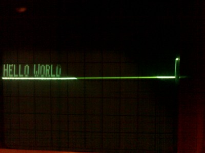
thrashbarg-sym1-crt_display2.jpeg [ 122.72 KiB | Viewed 3885 times ]


However, I can't say I really understand how it's done - somehow an interrupted sawtooth creates a raster output. There are only two wires: sync, and display. This is not a TV scan or an X-Y mode.

We're directed to chapter 7 of the manual, which has some diagrams and explanation, but I don't quite get it.
https://deramp.com/downloads/mfe_archiv ... f#page=106

Edit: perhaps this helps
Quote:
The sawtooth is shown below and forms the columns of the display


In other words, the raster is a series of steep up-sloping lines, which we think of as vertical. The lines are interrupted by clamping to zero which is why we see a strong flat line below the one-line display.

Over on the VCFed forums, thrashbarg writes
Quote:
To operate it get the data for the next line and shift it through point B, when you've shifted 8 bits, pulse point A. This will reset the vertical sweep. When all of the lines are drawn (160 is the standard, 32 characters at 5 lines) pulse point A for a very long time, enough to create a noticeable pulse on the oscilloscope. This pulse is used to sync the display to the sweep. If you set the oscilloscope trigger to negative edge then the pulse itself won't be visible at the start of the sweep, so you'll just have text.


Last edited by BigEd on Tue Dec 20, 2022 3:47 pm, edited 1 time in total.

Top
 Profile  
Reply with quote  
PostPosted: Tue Dec 20, 2022 3:47 pm 
Offline

Joined: Sat Feb 12, 2022 11:03 pm
Posts: 39
I'll take a look, and yes, I have used the included driver in the manual, which is what my oscilloscope output shows.

That photo is very very promising!


Top
 Profile  
Reply with quote  
PostPosted: Tue Dec 20, 2022 3:49 pm 
Offline
User avatar

Joined: Thu Dec 11, 2008 1:28 pm
Posts: 10793
Location: England
(Edited my reply slightly!)

I think you might need to set your scope so it doesn't draw the steep vertical lines which return the raster to the zero baseline. You need to see just the tops of the pulses.

Edit: You need a very slow timebase, of 50ms.


Top
 Profile  
Reply with quote  
PostPosted: Tue Dec 20, 2022 4:32 pm 
Offline

Joined: Wed Nov 11, 2020 10:42 pm
Posts: 96
Location: Kelowna Canada
I recall having done this on my SYM-1 with a very old scope in 1981. If I recall correctly it looked about like the picture of the display. The details are lost in the mists of time. I have the same scope now as you have, but I had removed enough parts from that circuit on the SYM to reclaim the PB2 line for the clock signal in a keyboard driver that I created for Cortron keyboard with serial non-ASCII output. I'm not sure that I could make the scope interface work again to try it out. I still have the SYM-1 (now with a KTM3-80 but the Cortron is gone). I would commend you to look at the topic on Symbiosys (viewtopic.php?f=2&t=1696) for connecting a CF card interface to your SYM. (Needs RAE though).


Top
 Profile  
Reply with quote  
PostPosted: Tue Dec 20, 2022 7:30 pm 
Offline
User avatar

Joined: Fri Aug 30, 2002 1:09 am
Posts: 8428
Location: Southern California
BigEd wrote:
I think you might need to set your scope so it doesn't draw the steep vertical lines which return the raster to the zero baseline. You need to see just the tops of the pulses.

I think that's going to be the key, right there.  I suspect most digital 'scopes are going to fill in the vertical lines between adjacent points whose Y value is radically different.  You might need an analog oscilloscope for this to work.

_________________
http://WilsonMinesCo.com/ lots of 6502 resources
The "second front page" is http://wilsonminesco.com/links.html .
What's an additional VIA among friends, anyhow?


Top
 Profile  
Reply with quote  
PostPosted: Wed Dec 21, 2022 3:51 pm 
Offline

Joined: Sat Feb 12, 2022 11:03 pm
Posts: 39
okwatts wrote:
I recall having done this on my SYM-1 with a very old scope in 1981. If I recall correctly it looked about like the picture of the display. The details are lost in the mists of time. I have the same scope now as you have, but I had removed enough parts from that circuit on the SYM to reclaim the PB2 line for the clock signal in a keyboard driver that I created for Cortron keyboard with serial non-ASCII output. I'm not sure that I could make the scope interface work again to try it out. I still have the SYM-1 (now with a KTM3-80 but the Cortron is gone). I would commend you to look at the topic on Symbiosys (viewtopic.php?f=2&t=1696) for connecting a CF card interface to your SYM. (Needs RAE though).


As for Symbiosys, I have looked at it and I have built up the card and ssd, however, I couldn't get it to work lol. I instead am using an edited SYMDOS with a few extra routines. I will definitely try to use symbiosys in the future!


Top
 Profile  
Reply with quote  
Display posts from previous:  Sort by  
Post new topic Reply to topic  [ 7 posts ] 

All times are UTC


Who is online

Users browsing this forum: No registered users and 9 guests


You cannot post new topics in this forum
You cannot reply to topics in this forum
You cannot edit your posts in this forum
You cannot delete your posts in this forum
You cannot post attachments in this forum

Search for:
Jump to: