6502.org Forum  Projects  Code  Documents  Tools  Forum
It is currently Sat Apr 27, 2024 4:01 pm

All times are UTC


Post new topic Reply to topic  [ 8 posts ] 
Author Message
PostPosted: Thu May 18, 2017 2:14 pm 
Offline

Joined: Wed Jan 08, 2014 3:31 pm
Posts: 565
I have Rich Cini's SBC-2.7 which shares the same expansion pin out as Darl's original design and I run it at 1 MHz. I've bread boarded an AY-3-8910 expansion and want to make it permanent on some Veroboard. One approach is to build a card that directly plugs into the expansion header, and the other is to use a short ribbon cable between the boards.

The pros of the ribbon able is that it gives flexibility in how I mount the card, and ribbon cables are easily available. The downside is that it will add noise and an untidy ribbon cable.

The direct connection require a 2x25 female header with some extra long pins to give some space between the motherboard and daughter card. Those aren't easy to find, and this only allows one orientation in mounting. However I would think this would introduce minimal noise.


Top
 Profile  
Reply with quote  
PostPosted: Thu May 18, 2017 3:53 pm 
Offline
User avatar

Joined: Thu May 28, 2009 9:46 pm
Posts: 8144
Location: Midwestern USA
Martin_H wrote:
I have Rich Cini's SBC-2.7 which shares the same expansion pin out as Darl's original design and I run it at 1 MHz. I've bread boarded an AY-3-8910 expansion and want to make it permanent on some Veroboard. One approach is to build a card that directly plugs into the expansion header, and the other is to use a short ribbon cable between the boards.

The pros of the ribbon able is that it gives flexibility in how I mount the card, and ribbon cables are easily available. The downside is that it will add noise and an untidy ribbon cable.

The direct connection require a 2x25 female header with some extra long pins to give some space between the motherboard and daughter card. Those aren't easy to find, and this only allows one orientation in mounting. However I would think this would introduce minimal noise.

If the ribbon cable is arranged so there is a ground between each signal lead and the next you can get a little bit of noise immunity. However, unless you have enough drive at your expansion port the cable's capacitance will do you in.

For long pins you could look at various Mill-Max offerings. They produce a series that is approximately 0.018 inches in diameter and will safely plug into DIp sockets, as well as strip plugs.

Another possibility would be to use a card edge and a compatible edge connector a la the cartridge port of the Commodore 64. Such an arrangement produces slightly lower losses than pins and header but of course means using a PCB with a properly prepared edge.

_________________
x86?  We ain't got no x86.  We don't NEED no stinking x86!


Top
 Profile  
Reply with quote  
PostPosted: Thu May 18, 2017 6:46 pm 
Offline
User avatar

Joined: Fri Aug 30, 2002 1:09 am
Posts: 8428
Location: Southern California
For long pins to plug into a socket, here's what I've done. Look at Mouser's catalog page at http://www.mouser.com/catalog/catalogusd/648/1674.pdf, top-left area, 11th through 14th lines, where the tail length is .410", .510", .610", and .910". The "mating length" is only the standard .235"; but you can turn it over and solder the mating part into the board, and use the long tail for plugging into the socket. Now with the insulator thickness plus the socket, you can get up to nearly an inch between boards.

_________________
http://WilsonMinesCo.com/ lots of 6502 resources
The "second front page" is http://wilsonminesco.com/links.html .
What's an additional VIA among friends, anyhow?


Top
 Profile  
Reply with quote  
PostPosted: Thu May 18, 2017 11:47 pm 
Offline

Joined: Wed Jan 08, 2014 3:31 pm
Posts: 565
Thanks for the replies. I will go with the extra tall headers and a direct connection.


Top
 Profile  
Reply with quote  
PostPosted: Fri May 19, 2017 7:59 am 
Offline

Joined: Sat Jul 28, 2012 11:41 am
Posts: 442
Location: Wiesbaden, Germany
At 1MHz I wouldn't worry too much about ribbon cables. Remember the ATA interface in the PC connecting up to 2 HDDs. 16 bit wide 40 pin UDMA cables managed to transfer 33 MB/s, with a ground wire between each signal up to 166 MB/s.

_________________
6502 sources on GitHub: https://github.com/Klaus2m5


Top
 Profile  
Reply with quote  
PostPosted: Sat May 20, 2017 5:27 am 
Offline
User avatar

Joined: Thu May 28, 2009 9:46 pm
Posts: 8144
Location: Midwestern USA
Klaus2m5 wrote:
At 1MHz I wouldn't worry too much about ribbon cables. Remember the ATA interface in the PC connecting up to 2 HDDs. 16 bit wide 40 pin UDMA cables managed to transfer 33 MB/s, with a ground wire between each signal up to 166 MB/s.

...and single-ended SCSI can go 40MB/second on a six meter long cable. However, the reason it is possible is due to the bus' low characteristic impedance (~110 ohms) and high drive levels. Drive per signal lead is around 45mA.

_________________
x86?  We ain't got no x86.  We don't NEED no stinking x86!


Top
 Profile  
Reply with quote  
PostPosted: Tue May 23, 2017 5:35 pm 
Offline
User avatar

Joined: Wed Sep 03, 2003 6:53 pm
Posts: 150
Location: Long Island, NY
There are too many signal pins on the expansion bus connector to have GND on even pins like a floppy or SCSI ribbon cable. I carried the expansion connector over unmodified from the original design. There is room, with a little tightening of the design, for the required buss driver chips, or you could build an intermediate buffer board like was used on the TRS-80 Model I expansion interface connector.

_________________
Rich Cini
Build Master and maintainer of the Altair32 Emulation project
http://cini.classiccmp.org
http://altair32.classiccmp.org


Top
 Profile  
Reply with quote  
PostPosted: Fri Aug 24, 2018 2:26 pm 
Offline

Joined: Thu Aug 23, 2018 7:10 am
Posts: 89
Location: CyberBunker
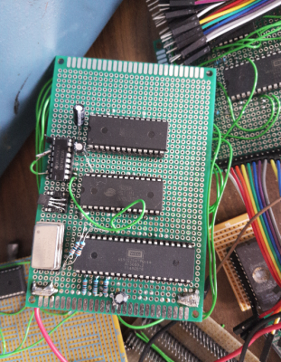
it's really not that critical, this thing is one big mess of wires (the front kinda gives an impression of the back, which has piles of telephone patching wires 5cm high sticking out of it ;) and has successfully been running it's memory test and rom checksums at 2 and 4mhz for over a week with zero errors (8mhz also still seems to work but the at28c256-15 isn't specified up to that speed it seems). both with an nmos 6502B (driving cmos inputs at that) and a 65C02. the issues are more with the radio interference that comes -out- of it :P (it does seem to do a pretty nice job at transmitting am broadcast radio while it's at it ;) pretty much all those old commodore boards also just spell 'big antenna' all over them, no bus termination, no nothing, buses a mile long.
Attachment:
6502.png
6502.png [ 786.53 KiB | Viewed 5984 times ]
a bit of flatcable is nothing to worry about. unless it's more than a meter in total or so. IDE isn't terminated and runs at 33mhz-ish, scsi is terminated, but will happily run on flatcables up to 3 meters long. as the test board shows you can take the crappyness of your design a looong way before it starts to affect performance.


Top
 Profile  
Reply with quote  
Display posts from previous:  Sort by  
Post new topic Reply to topic  [ 8 posts ] 

All times are UTC


Who is online

Users browsing this forum: No registered users and 3 guests


You cannot post new topics in this forum
You cannot reply to topics in this forum
You cannot edit your posts in this forum
You cannot delete your posts in this forum
You cannot post attachments in this forum

Search for:
Jump to: