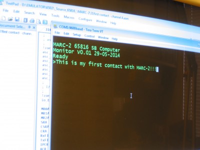
I'd like to present MARC-2.
Attachment:
 CRW_0048.jpg [ 520.63 KiB | Viewed 8186 times ]
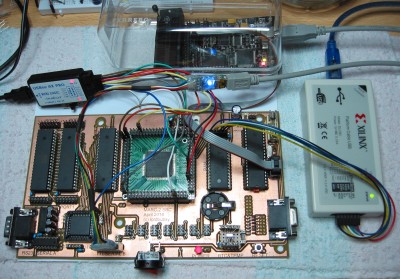
MARC-2 is a ROM-less SBC largely based on a combination of Daryl Rictor's SBC-3, SBC-4 and some own ideas. I chose a larger CPLD to make MARC-2 as
flexible as possible. By attaching headers to all pins of the CPLD, MARC-2 is also easily
expandable. A daughter board can be created by female connectors at the bottom and male headers at the top of a PCB. This way the signal lines are as short as possible. Talking about PCB and soldering, I have made this PCB at home but have to say that it’s my limit I'm willing to do at home. There are 720 pads and 168 vias so 888 holes to drill! The vias are hand soldered on the top and the back of the PCB with a very thin wire. Soldering all pads, vias and the expansion headers, I counted 1344 soldering joints. When everything works the way it was intended and all errors are removed, I likely will use a PCB house and considering a four layer board.
Attachment:
 CRW_0035.jpg [ 1.12 MiB | Viewed 8186 times ]
I've used the following IC's:
• CPU WDC65C816S
• SRAM AS6C4008 512Kb
• 'ROM' ATMega1284P (AVR)
• VIA0 WDC65C22S
• VIA1 WDC65C22S
• DUART SC26C92
• RTC RV-3049-C2
• CPLD XC95288XL TQ144
• RS232 MAX232
Operation:
The AVR runs at 14.7456MHz and provides that frequency to the CPLD at all times. The AVR senses the reset button and provides the overall reset signal to the CPLD. During RESET, the AVR copies the 16kB ROM image from its flash memory to the SRAM, which takes 79ms. After RESET the AVR is tri-stated. This way there is no (E)EPROM needed. The SRAM can be easily expanded to 1MB by piggy backing an extra SRAM on top of it, the CS signal is already provided on a solder pad nearby.
The CLOCK is divided by 2 so that PHI2 is 7.3728MHz. I'd hoped for this speed although I know it could probably be doubled. The 14.7456MHz also serves as pixel clock for the VGA interface that will be implemented later. The 3.6864MHz for the DUART I also wanted to get from the CPLD, but instead of that, a quartz with two 22pF caps to ground takes care of it.
The CPU and SRAM are connected separately to the CPLD. This alone costs 51 I/O lines and some extra logic programming but gives the advantage of having VGA and DMA later on.
The memory map looks like this:
Code:
RAM: $000000-$00BEFF
DUART: $00BF00-$00BF0F
VIA0: $00BF10-$00BF1F
VIA1: $00BF20-$00BF2F
IRQREG: $00BFFF-$00BFFF (testing this at the moment)
RAM: $00C000-$07FFFF
I.e. there is RAM from $000000-$07FFFF except for the I/O page $00BF00-$00BFFF
Both VIA's are functional and free for use, however, nothing is connected to it right now.
The DUART is connected on channel A to a traditional RS232 port and channel B to a USB to TTL serial bridge. It's running by polling or interrupt based with 115200 baud without problems. I use TeraTerm to communicate with MARC-2.
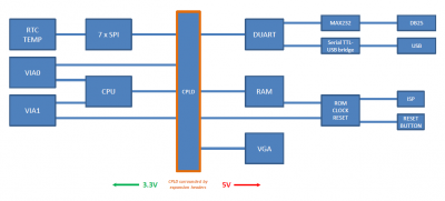
Here is a simple block diagram:
Attachment:
 BLOCK01.png [ 24.07 KiB | Viewed 8186 times ]
The CPLD is configured with "Slow Output Slew Rate" and "Low Macrocell Power Setting". These settings reduce power consumption and noise. MARC-2 draws only 92mA from the USB port and there is almost no heat generated from the IC's. The MAX232 and the AVR get warm the most.
I have full control over MARC-2 by means of 3 USB devices:
• AVR DRAGON to update MARC-2's ROM image
• Xilinx USB cable to update the behavior of MARC-2
• USB to TTL serial to communicate with MARC-2 itself and
to provide 5V power
The development chain is extremely short and I use the following programs to update MARC-2's bios:
• TextPad with syntax highlighting (free text editor)
• ACME 65xxx cross assembler (free assembler for creating a 16kB rom.bin)
• bin2db.exe (C program which converts rom.bin to rom.inc)
• avrasm2.exe (ATMEL's assembler which assembles and includes rom.inc to the AVR firmware)
• atprogram.exe (ATMEL's programmer which flashes the AVR)
This whole cycle takes two mouse clicks and a few seconds to complete. It's also very convenient that the SBC will be reset after programming the AVR. Until I have a decent BIOS with file transfer and an external storage device, I'll continue using this method.
To program the CPLD I use ISE 10.1 SP3 which is freely available as a full version and is the last one which supports ABEL (and parallel programmer if preferred).
Pitfalls:
First, soldering a 144 pin 0.5mm pitch CPLD to the adapter board was a challenge I had to dare taking. Those adapter boards are fairly cheap and I first tried it with some cheaper CPLD's before I tried the XC95288XL. Second, the XC95288XL brings the problem with 3.3V vs 5V with it. While supplied with 3.3V, the CPLD accepts 5V to its I/O lines. Third, programming the CPLD I found and still find a real challenge. Because everything is connected to the CPLD, everything has to be taken care of while programming the logic. Although it seems to work correctly, I'm not 100% sure it really is.
To-do:
IRQ register. I've connected the IRQ lines of VIA0, VIA1, DUART, RTC and later internally 65SPI and VGA to the CPLD. It's my intention to create a register to determine which IRQ has occurred.
65SPI: This will take about 21% of the CPLD's resources and provide 8 SPI interfaces of which one is connected to the RTC on the board itself.
VGA: I've connected HSYNC, VSYNC and 8 CPLD pins to a resistor DAC which is connected to RGB of the VGA connector. This should provide 256 colors. The timing to connect the right byte of SRAM to the VGA DAC at the right time is the task to be solved. I estimate it will take at least 20% of the CPLD's resources.
DMA: The CPLD controls the CPU and RAM buses separately. Although having the ability to do something with DMA, I'm not sure what will be useful to do with it. Perhaps someone has some input?
Wait-states: In time I'd like to make one or two daughter boards with two SID's, MIDI, IDE, PS/2 keyboard interface, an AY-3-8912 GI sound chip and an SP0256A-AL2 speech chip. For some of those devices I have to make use of wait-states, which will be provided by the CPLD. At the moment there are 16 I/O lines for use, so plenty to expand.
Software:
Luckily the '816 accepts 6502 code and acts like a one. So I began to test the address lines and I/O devices.
So far I programmed:
Reset routine
Test some toggling address lines
Test some toggling VIA pins
Test a toggling DUART I/O pin
Polled DUART routines
My own attempt of a ML monitor
Furthermore I've adapted:
BDD's interrupt based DUART routines with hardware handshaking
BDD's Supermon816
Daryl's Apple II based ML monitor (a few different versions)
Lee's EhBASIC
WozMon (Apple I monitor)
Attachment:
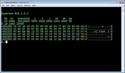 Supermon816.png [ 27.65 KiB | Viewed 8186 times ]
I've learned a LOT during the last year on this forum and I'd like to thank everyone who has helped me to make this happen. But I'm not there yet, the fun has just started. Now I have the base to start experimenting with all those IC's.
For instance, I compared a basic program to generate the prime numbers up to 997. The C64 took 123 seconds to complete, MARC-2 needed only 7 seconds!
Attachment:
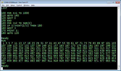 EhBASIC.png [ 42.04 KiB | Viewed 8186 times ]
Edit: corrected some minor errors.


