6502.org Forum  Projects  Code  Documents  Tools  Forum
It is currently Mon May 20, 2024 8:30 pm

All times are UTC


Post new topic Reply to topic  [ 13 posts ] 
Author Message
PostPosted: Sat May 18, 2024 10:03 am 
Offline

Joined: Wed Nov 16, 2011 9:39 am
Posts: 34
I have been working on a VGA sync circuit as a first step to add display functionality to my SBC http://forum.6502.org/viewtopic.php?f=1&t=8062

After trying out different counter chips and solutions I found one that is working pretty well (a slightly modified version of the one made by James Sharman, https://youtu.be/KSuEKRjmtbw?si=FhozC73dRdo9pjk4 )

But, the top part is crooked, as can be seen in the image. I wonder if it is an artefact of a noisy circuit or if there is something wrong with the screen? It's 19 years old after all. The picture is rock stable in itself, just crooked at the top. I would expect noise to cause flickering or general instability but perhaps this can happen too?

The sync circuit made on solderless breadboards and the signal is pretty noisy according to my scope, as to be expected when not special care is taken to counteract the artefacts of solderless breadboards. I aim to clean it up somewhat and later build real PCBs for it but first I want to identify if the problem could be something else entirely. If it is due to noise I might even go for the PCB option sooner than later because having this on solderless breadboard is not that great anyway (I actually hate working with solderless breadboards but it's good for figuring out how chips interact which eachother). Any ideas?

I have attached a rough outline of the circuit exported from Kicad. In the photo I am not loading R G B but rather letting the 74HC163 that is connected to the VGA-connector count for each clock cycle to create the RGB-pattern, but the same crookedness happens if I connect a constant color which is loaded all the time.

EDIT: The inverters are not present on the breadboards, they were added in the schematics as I might be delaying the clock signals in the future.


Attachments:
File comment: VGA circuit
vga.png
vga.png [ 237.58 KiB | Viewed 127 times ]
File comment: Crooked image
IMG_9699.jpg
IMG_9699.jpg [ 650.72 KiB | Viewed 127 times ]
Top
 Profile  
Reply with quote  
PostPosted: Sat May 18, 2024 10:18 am 
Offline

Joined: Wed Nov 16, 2011 9:39 am
Posts: 34
Some info about the EEPROM contents. The sync clock (SCLK) runs at 25.175/16 MHz. The /RESET bit is set on byte 26249 which corresponds to 800*525/16 pixel clocks starting from 0. The DISPLAY bit is stored one byte before it is used due to it being clocked into the 74HC163N from the 74HC574 latch (1 SCLK delay).


Top
 Profile  
Reply with quote  
PostPosted: Sat May 18, 2024 2:21 pm 
Offline
User avatar

Joined: Fri Aug 30, 2002 9:02 pm
Posts: 1687
Location: Sacramento, CA
Assuming the hardware is working correctly, my best guess is to take a look at the vertical sync timing, since its tearing only at the top.

thanks!
Daryl

_________________
Please visit my website -> https://sbc.rictor.org/


Top
 Profile  
Reply with quote  
PostPosted: Sat May 18, 2024 3:17 pm 
Offline

Joined: Fri Mar 18, 2022 6:33 pm
Posts: 449
I seem to remember there's a potential problem chaining a bunch of 163 counters together like that.

(Here it is in the data sheet, on page 12: https://www.ti.com/lit/ds/symlink/sn54hc163.pdf)

George (gfoot) uses a pair of `590 counters to drive the EEPROM in his design (here: https://hackaday.io/project/175434-worl ... ga-circuit), and I followed his example with mine (here: viewtopic.php?f=4&t=7633).

What are those series resistors for on your sync signals?

_________________
"The key is not to let the hardware sense any fear." - Radical Brad


Top
 Profile  
Reply with quote  
PostPosted: Sat May 18, 2024 3:42 pm 
Offline

Joined: Wed Nov 16, 2011 9:39 am
Posts: 34
8BIT wrote:
Assuming the hardware is working correctly, my best guess is to take a look at the vertical sync timing, since its tearing only at the top.

thanks!
Daryl


Hm I will double check the vertical sync timing code when I get home. Late night Python coding is not a bullet-proof activity :lol:


Top
 Profile  
Reply with quote  
PostPosted: Sat May 18, 2024 3:46 pm 
Offline

Joined: Wed Nov 16, 2011 9:39 am
Posts: 34
Paganini wrote:
I seem to remember there's a potential problem chaining a bunch of 163 counters together like that.

(Here it is in the data sheet, on page 12: https://www.ti.com/lit/ds/symlink/sn54hc163.pdf)

George (gfoot) uses a pair of `590 counters to drive the EEPROM in his design (here: https://hackaday.io/project/175434-worl ... ga-circuit), and I followed his example with mine (here: viewtopic.php?f=4&t=7633).

What are those series resistors for on your sync signals?


There is a glitch, but according to the specification it is only relevant for speeds over 18 MHz. I am running the circuit at 1.5 MHz so in theory it shouldn't[tm] be an issue. I tried to use 590's in the beginning but found the double clock annoying and couldn't really get it to work satisfactory. Now it seems to be mostly working so I am hesitant to tear it apart a fourth time :D (this is the second '163 build, previously also built one '161 version and one '590 version :shock: )

The series resistors is a "i read it at some random forum that you should put some 47 ohm:ish resistors on sync signals" addition. They make no apparent difference what I can see so I might remove them again.


Top
 Profile  
Reply with quote  
PostPosted: Sat May 18, 2024 4:47 pm 
Offline

Joined: Tue Jul 05, 2005 7:08 pm
Posts: 995
Location: near Heidelberg, Germany
8BIT wrote:
Assuming the hardware is working correctly, my best guess is to take a look at the vertical sync timing, since its tearing only at the top.

thanks!
Daryl


From my experience with such timing settings I also think this is a timing problem, and most likely vertical timing, I agree.

André

_________________
Author of the GeckOS multitasking operating system, the usb65 stack, designer of the Micro-PET and many more 6502 content: http://6502.org/users/andre/


Top
 Profile  
Reply with quote  
PostPosted: Sat May 18, 2024 6:39 pm 
Offline

Joined: Fri Mar 18, 2022 6:33 pm
Posts: 449
JohanFr wrote:
There is a glitch, but according to the specification it is only relevant for speeds over 18 MHz. I am running the circuit at 1.5 MHz so in theory it shouldn't[tm] be an issue. I tried to use 590's in the beginning but found the double clock annoying and couldn't really get it to work satisfactory. Now it seems to be mostly working so I am hesitant to tear it apart a fourth time :D (this is the second '163 build, previously also built one '161 version and one '590 version :shock: )
Yeah, the 590 register can be kind of a pain. Sure is nice to only have 2 counter ICs per EPROM rather than 5 or 6 though!

Quote:
The series resistors is a "i read it at some random forum that you should put some 47 ohm:ish resistors on sync signals" addition. They make no apparent difference what I can see so I might remove them again.
Aha! LOL! I was just curious; I've never seen those before.

Here's the timing side of my VGA board. It's very similar to George's. I added a few signals, because my output side is different (using a character ROM to generate a text-only display).
Attachment:
Screen Shot 2024-05-18 at 12.50.41 PM.png
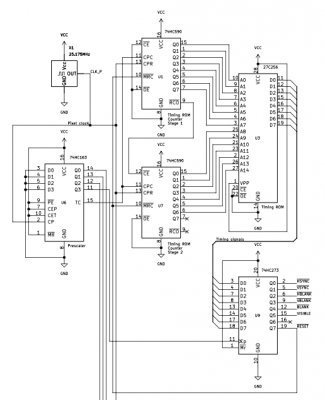
Screen Shot 2024-05-18 at 12.50.41 PM.png [ 69.37 KiB | Viewed 80 times ]
VGA is kind of simple, in a way. There are really only two problems you can have. If your timing signals (HSYNC, VSYNC) are out of spec, the display won't lock *at all* and you get nothing. You clearly are not suffering from this problem. :P If your timing signals are good, then the display will - mindlessly - present whatever comes in over the RGB lines. (This is assuming your display is a good one - hopefully by now you plugged it into something else to make sure it actually works! :) ) That means that *the display itself* is a kind of debugging of your output side logic.

In your picture, I see 40 columns that are good for a few scanlines, then each scanline gets off by one more pixel every line until everything has moved over more than one column, and then it *moves back the other way* a pixel at a time, but not every scanline, until it settles in and remains stable for the rest of the frame. I'm not sure which area is the correct one - do you expect to see a green bar or a black bar in the first column? Either way, this seems an awful lot like an out of phase counter.

Looking at your output register, it's clocked by SCLOCK, which is ~1.57 MHz, and reset by DISPLAY. I'd take a look at those two signals in addition to checking to make sure your timing ROM is correct. One thing you might try is setting the whole screen to white. Any irregular black areas will tell you about your front / back porch and blanking timing. Also, what happens if you never reset the output register? (This will show you exactly where the monitor thinks each frame begins and ends.) Or, what happens if you don't use the output register at all? (Just tie RGB high through resistors.) Do you get a square, or do you still see distortion?

Etc. :)

_________________
"The key is not to let the hardware sense any fear." - Radical Brad


Top
 Profile  
Reply with quote  
PostPosted: Sat May 18, 2024 7:40 pm 
Offline

Joined: Wed Nov 16, 2011 9:39 am
Posts: 34
Timing code looks correct, but I will revisit it a few more times. Monitor seems to think it's displaying 640x481 pixels so there is definitely a timing issue.

I tested with white screen at it looks very similar to the colored screen, it's off to the right in the beginning then a bit to the left. Removing reset seems to do nothing for the signal but the image is never displayed. (EDIT: of course it does nothing for the signal as the sync is not routed through the '163 :oops: )

Tying the RGB directly to Vcc (Via resistor) removes that color from display, I assume because of reference voltage getting screwed up.

I might need to bring out the scope.

Perhaps I should try bypassing the 74HC163 altogether and hardcode some RGB values into the ROM instead.

EDIT: Sorry about the rotated image, courtesy of Apple doing nondestructive rotation in the OS without telling so.


Attachments:
image0.jpeg
image0.jpeg [ 407.98 KiB | Viewed 73 times ]
Top
 Profile  
Reply with quote  
PostPosted: Sat May 18, 2024 8:05 pm 
Offline

Joined: Wed Nov 16, 2011 9:39 am
Posts: 34
Hmm it might be the sync code after all and the fact that the "visible" flag comes to the RGB-latch one cycle too late. I can see an additional block of white at the bottom and when I look at the code I haven't taken in account this fact for when the vertical lines transition into front porch. I'll do some Python tinkering and test.

Edit: Or I'll just bypass the '574 for the reset signal and let it go directly from EEPROM to the '163 and remove any special case coding in the sync code.


Top
 Profile  
Reply with quote  
PostPosted: Sat May 18, 2024 9:20 pm 
Offline

Joined: Wed Nov 16, 2011 9:39 am
Posts: 34
I managed to solve it. If I trigger the reset at the SECOND to last position in the ROM code rather than last one it works. Probably related to the fact that the reset is latched and delayed one clock. I'm too tired to understand why it worked at all at before but maybe tomorrow me will figure that out :)

Thanks for all the help and suggestions!


Attachments:
IMG_9706.jpg
IMG_9706.jpg [ 846.71 KiB | Viewed 60 times ]
Top
 Profile  
Reply with quote  
PostPosted: Sat May 18, 2024 9:52 pm 
Offline

Joined: Fri Mar 18, 2022 6:33 pm
Posts: 449
Awesome! That looks great!

I've also suffered from "rotated picture" syndrome before; I find that if I open the image up in Preview, rotate it through 360 degrees, then save it, whatever it was that got confused about the orientation is fixed, and it displays fine here after I upload.

Just a curiosity, I notice that you have a different set of color bars than before. Did you change the output stage also?

_________________
"The key is not to let the hardware sense any fear." - Radical Brad


Top
 Profile  
Reply with quote  
PostPosted: Sat May 18, 2024 10:41 pm 
Offline

Joined: Wed Nov 16, 2011 9:39 am
Posts: 34
Paganini wrote:
Awesome! That looks great!

I've also suffered from "rotated picture" syndrome before; I find that if I open the image up in Preview, rotate it through 360 degrees, then save it, whatever it was that got confused about the orientation is fixed, and it displays fine here after I upload.

Just a curiosity, I notice that you have a different set of color bars than before. Did you change the output stage also?


Excellent tip, thank you! :D

Ah yes it's a different set of pixels, coming from the EEPROM as I was debugging. But it works now with a solid screen coming from the '163 pixel latch as well. I have thought about it some more and I think I have overcomplicated things by running the reset signal through the '574. As the '163s are synchronous themselves I should be able to send the reset signal directly from the EEPROM and then be able to send the reset signal at the last pixel of the frame. But that is tomorrow's problem. :D

Now the fun part starts, I hope. As for x- and y-counters I might consider the '590s again, now that i have an excellent debugging tool when the sync is working. :)


Top
 Profile  
Reply with quote  
Display posts from previous:  Sort by  
Post new topic Reply to topic  [ 13 posts ] 

All times are UTC


Who is online

Users browsing this forum: No registered users and 4 guests


You cannot post new topics in this forum
You cannot reply to topics in this forum
You cannot edit your posts in this forum
You cannot delete your posts in this forum
You cannot post attachments in this forum

Search for:
Jump to: