6502.org Forum  Projects  Code  Documents  Tools  Forum
It is currently Sat Apr 27, 2024 1:57 pm

All times are UTC


Post new topic Reply to topic  [ 47 posts ]  Go to page Previous  1, 2, 3, 4  Next
Author Message
PostPosted: Sat Dec 02, 2023 8:15 pm 
Offline

Joined: Mon Jan 19, 2004 12:49 pm
Posts: 660
Location: Potsdam, DE
My word, this has turned out to be a busy board: 160x100mm
Attachment:
NeoSTMlayout.png
NeoSTMlayout.png [ 253.66 KiB | Viewed 1541 times ]

Same board, looks a bit cleaner in the 3d render when you can't see all the gory details:
Attachment:
NeoSTM3d.png
NeoSTM3d.png [ 309.25 KiB | Viewed 1541 times ]

This needs some prototype testing before I order the boards; there a lot going on (most detailed in previous posts):
  • 2.5MHz 65c02 + 65c22
  • 64k RAM (except for 128 bytes at 0xff00 for the 65c22)
  • 384 x 300 pixel addressed SVGA video output
  • DMA interface to an STM32L073 providing serial UART, PS/2 mouse and keyboard, and microSD filesystem
Most of this is still wishlist, but I'll start writing software once I have the rest of the system up. Also there's still some work to do labelling things on the PCB, but I'm away from home for a couple of weeks so it'll have to wait.

Neil


Top
 Profile  
Reply with quote  
PostPosted: Sat Dec 02, 2023 8:28 pm 
Offline
User avatar

Joined: Thu May 28, 2009 9:46 pm
Posts: 8144
Location: Midwestern USA
barnacle wrote:
I'm doing my best to age disgracefully...

I’m way ahead of you guys on that.  :x

_________________
x86?  We ain't got no x86.  We don't NEED no stinking x86!


Top
 Profile  
Reply with quote  
PostPosted: Sat Dec 02, 2023 8:34 pm 
Offline
User avatar

Joined: Thu May 28, 2009 9:46 pm
Posts: 8144
Location: Midwestern USA
fachat wrote:
I can't judge the situation they were in at that time, but from today's point of view, inmy humble opinion, they've hardware-optimized themselves into a corner were difficult to get out of.

One only needs to look at the 65C816’s hardware behavior in emulation mode to see that.  Mensch wanted to permanently design out the hinky bus behavior of the 6502 from the 816, but had to keep it so the ][GS would be able to use Apple ][ accessories.  The VDA and VPA outputs at least gave a system designer a way to avoid problems caused by the anomalous bus states during instruction execution that Wozniak was depending on in some of his designs.

_________________
x86?  We ain't got no x86.  We don't NEED no stinking x86!


Top
 Profile  
Reply with quote  
PostPosted: Thu Dec 28, 2023 7:54 pm 
Offline

Joined: Mon Jan 19, 2004 12:49 pm
Posts: 660
Location: Potsdam, DE
Well, in between painting this, and laying a floor that, and carrying boxes the other... I managed to knock together a little bit of test hardware. And, woohoo, the SVGA line timing works and is spot on... though the circuit looks like it was put together by an inebriated spider...
Attachment:
1703792192139.jpg
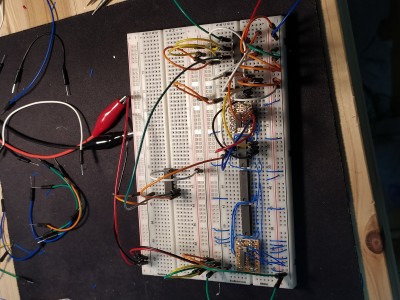
1703792192139.jpg [ 4.05 MiB | Viewed 834 times ]
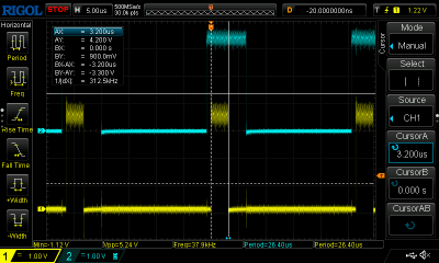
Line sync is 3.2us:
Attachment:
DS1Z_QuickPrint21.png
DS1Z_QuickPrint21.png [ 56.74 KiB | Viewed 834 times ]

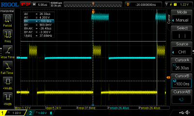
Line blanking is a touch longer than spec; I'm using only 384 of my 400 horizontal pixels:
Attachment:
DS1Z_QuickPrint22.png
DS1Z_QuickPrint22.png [ 57.01 KiB | Viewed 834 times ]

And the line timing is exactly 26.4us:
Attachment:
DS1Z_QuickPrint23.png
DS1Z_QuickPrint23.png [ 56.1 KiB | Viewed 834 times ]


All this in just six and a bit chips (there's a seventh chip in there to generate the load pulse for the parallel to serial chip, but I didn't count that :) ) and it's perhaps interesting in that it uses - after the initial 20MHz tp 2.5MHz divider - ripple counters and decoders. The count always increments in such a way that there aren't any glitches that affect the outputs.

The field generator works in a similar, but not identical, way, so that's next to check if it fits on the board.

Neil


Top
 Profile  
Reply with quote  
PostPosted: Mon Jan 01, 2024 2:21 pm 
Offline

Joined: Mon Jan 19, 2004 12:49 pm
Posts: 660
Location: Potsdam, DE
Have I mentioned how much I like prototype boards? Spent half a day yesterday trying to track down what looks like a floating input - signals moving with respect to each other at mains-like frequencies - before giving up in disgust... and today I just turned it on and it's working perfectly... :shock: :evil:

It's not pretty, though...
Attachment:
1704117805021.jpg
1704117805021.jpg [ 4.62 MiB | Viewed 667 times ]


But the field sync and blanking are correct as close as the scope will measure at this resolution, with the exception that the sync pulse occurs one line earlier than it should to simplify the design (there should be one line of front porch after the active field ends).
Attachment:
DS1Z_QuickPrint25.png
DS1Z_QuickPrint25.png [ 46.99 KiB | Viewed 667 times ]

Attachment:
DS1Z_QuickPrint26.png
DS1Z_QuickPrint26.png [ 47 KiB | Viewed 667 times ]


Next step is to see if this will actually drive a flatscreen that's supposed to accept it. After that - I found a couple of 166's while tidying up to move next door, so I need to confirm to myself whether they latch on the edge. If they do, the circuit gets a lot simpler: I can lose two chips and use the spare second half of a timer. And at present, the board is quite complex enough, thank you; just under five hundred connections in the rat's nest.

Neil


Top
 Profile  
Reply with quote  
PostPosted: Mon Jan 01, 2024 5:59 pm 
Offline

Joined: Mon Jan 19, 2004 12:49 pm
Posts: 660
Location: Potsdam, DE
Woohoo!
Attachment:
1704131449676.jpg
1704131449676.jpg [ 3.54 MiB | Viewed 640 times ]

The colours are all over the place but that's not an issue at present; and it looks as if the line sync is at the wrong time (probably I picked line blank instead of line sync) but it's rock steady, no jitter.

The voltages on the output suggest that the monitor isn't terminated (I'm seeing 1.4v instead of the 0.7 I expect, on the cable) and weird things happen when I short out the series resistors: red or blue shorted turn the monitor off, but green shorted sets the green to what I'd expect as the right level. And it's all a bit gloomy... I wonder if (a) the termination is switchable on this monitor and (b) if it can take syncs-on-green.

Aye, something for tomorrow.

Neil

p.s. I won't be using colour in the final form, but rather monochrome with R=G=B
p.p.s if the sync is wrong the colours will be as it will be sampling black level at the wrong place...


Top
 Profile  
Reply with quote  
PostPosted: Mon Jan 01, 2024 9:19 pm 
Offline

Joined: Fri Jul 09, 2021 10:12 pm
Posts: 741
Sorry if I missed it but I don't think you posted a schematic of the output side of things, so it's hard to guess what's going on there. And as I think you were in broadcasting, I'm sure you know more about this than I do - but from my understanding, ideally you would produce a 0-1.4V signal and then pass it through 75 ohms in series, to the VGA connector. However, it usually works well enough to just pass 5V through about 470 ohms and rely on the monitor having exactly 75 ohms input termination. And make sure you ground all the individual ground return lines at your end, the monitor doesn't necessarily do that AFAIK.

Sometimes I have also passed hsync and vsync through larger resistors e.g. 5K or 10K, I don't know how they are supposed to be terminated.


Top
 Profile  
Reply with quote  
PostPosted: Mon Jan 01, 2024 9:37 pm 
Offline

Joined: Mon Jan 19, 2004 12:49 pm
Posts: 660
Location: Potsdam, DE
It's nothing exotic; just a 3.3v output driving through a series 270 ohm resistor. With the expected 75 ohm termination, that should give 3.3*75/(270+75) = 0.72v. Actually, it occurs to me that I'm driving signal - I just picked up a character counter bit - during blanking period. I'll put some blanking on the signal and see what happens. (This proof-of-concept on the proto board is only part of the overall circuit).

hsync and vsync are supposed to be 'TTL' but how close that is to real TTL is not specified in anything I've come across yet. I'm driving them from 3.3v CMOS with nothing in series. TTL is nominally 1.6mA to pull an input low - much less to pull it high.

Yes, normal video amp practice would be to generate a 1.4v signal and feed it through a 75 ohm series resistor, the connecting cable, and then a terminating 75 ohm impedance. That's not necessarily in the display; in the days of analogue video most professional equipment had a selectable high or 75 ohm input impedance so that they can be daisy-chained; only the last is terminated. The purpose of that final termination is to prevent echoes of the signal chasing back along the cable.

Neil

edit: a common design of distribution amplifier (DA) would have a low output impedance amplifier section with half a dozen 75 ohm outputs, each through its own resistor. It's a regular need to have the same signal in multiple places.


Top
 Profile  
Reply with quote  
PostPosted: Mon Jan 01, 2024 10:14 pm 
Offline

Joined: Fri Jul 09, 2021 10:12 pm
Posts: 741
barnacle wrote:
It's nothing exotic; just a 3.3v output driving through a series 270 ohm resistor. With the expected 75 ohm termination, that should give 3.3*75/(270+75) = 0.72v. Actually, it occurs to me that I'm driving signal - I just picked up a character counter bit - during blanking period. I'll put some blanking on the signal and see what happens. (This proof-of-concept on the proto board is only part of the overall circuit).
That would definitely cause the problem, I've seen that first hand - getting different intensities on different lines due to garbage being output during horizontal blanking. I'm not sure whether it's the hsync pulse itself, or a region around one of its edges, but blanking the porches is very much necessary.

I understand why this was the case in the days of composite sync, but for VGA I'm not sure why it can't just go with 0V being black, instead of being adaptive?


Top
 Profile  
Reply with quote  
PostPosted: Mon Jan 01, 2024 10:55 pm 
Offline
User avatar

Joined: Tue Feb 28, 2023 11:39 pm
Posts: 133
Location: Texas
barnacle wrote:
It's nothing exotic; just a 3.3v output driving through a series 270 ohm resistor. With the expected 75 ohm termination, that should give 3.3*75/(270+75) = 0.72v. Actually, it occurs to me that I'm driving signal - I just picked up a character counter bit - during blanking period. I'll put some blanking on the signal and see what happens. (This proof-of-concept on the proto board is only part of the overall circuit).


I'm sure you guys know this more than I do, but would it make sense to have all the voltage divider stuff up front on the card on the off chance that the monitor doesn't conform to norms?

My brain wants to drift towards using a transistor as a trim so that the current requirements don't need to flow through the ICs.

If I'm way off base let me know, I don't really know much about the analog side of the electronics fence.


Top
 Profile  
Reply with quote  
PostPosted: Tue Jan 02, 2024 5:51 am 
Offline

Joined: Mon Jan 19, 2004 12:49 pm
Posts: 660
Location: Potsdam, DE
Effectively that's what's happening, Yuri. Because the terminating resistor is (should be) built into the monitor input to avoid line reflections, you have two choices.

Number one is the canonical best approach: generate the signal, provide a low output impedance amplifier output at twice the required voltage (e.g. an emitter follower), and use a series 75 ohm resistor to match the termination. The voltage division is then between that 75 ohm and the 75 ohms to ground at the input, and so should provide the requisite 0.7v of signal at the monitor.

Number two is the lazy way, and based on the observation that for short cable runs, reflections are *probably* not an issue. In that case, the low output impedance amplifier is a TTL or CMOS gate, and the series resistor is calculated to give the desired voltage when it's part of a divider with the 75 ohm termination - in this case, with a 3v3 supply, 270 ohms is close enough.

Ideally, in either case, the video driver should be a separate chip - which I haven't done so far - and should certainly ensure that the video is black during video blanking - which I also didn't do. So that's a task for today.

Neil


Top
 Profile  
Reply with quote  
PostPosted: Tue Jan 02, 2024 6:00 am 
Offline

Joined: Mon Jan 19, 2004 12:49 pm
Posts: 660
Location: Potsdam, DE
gfoot wrote:
barnacle wrote:
<blanking>

I understand why this was the case in the days of composite sync, but for VGA I'm not sure why it can't just go with 0V being black, instead of being adaptive?


Probably because the same people that designed TVs also designed video monitors. Too much evolutionary baggage? A desire to provide maximum compatibility with what were initially very (or subtly) different standards being pushed?

A baseband composite video display (most likely a TV receiver) uses the height of the sync pulse to adjust the input gain so the video is the right size, and the relative height of the sync pulse and colour burst to calculate the colour gain. That way, the viewer gets the best picture, as close as possible to what left the TV station (though there's no accounting for NTSC!)

Given that the majority of early computer displays were home TVs it makes sense that people trying to push better quality monitors would have to make them compatible, even if they also included RGB inputs and/or separate syncs.

Neil


Top
 Profile  
Reply with quote  
PostPosted: Tue Jan 02, 2024 6:16 am 
Offline
User avatar

Joined: Tue Feb 28, 2023 11:39 pm
Posts: 133
Location: Texas
barnacle wrote:
Effectively that's what's happening, Yuri. Because the terminating resistor is (should be) built into the monitor input to avoid line reflections, you have two choices.

Number one is the canonical best approach: generate the signal, provide a low output impedance amplifier output at twice the required voltage (e.g. an emitter follower), and use a series 75 ohm resistor to match the termination. The voltage division is then between that 75 ohm and the 75 ohms to ground at the input, and so should provide the requisite 0.7v of signal at the monitor.

Number two is the lazy way, and based on the observation that for short cable runs, reflections are *probably* not an issue. In that case, the low output impedance amplifier is a TTL or CMOS gate, and the series resistor is calculated to give the desired voltage when it's part of a divider with the 75 ohm termination - in this case, with a 3v3 supply, 270 ohms is close enough.

Ideally, in either case, the video driver should be a separate chip - which I haven't done so far - and should certainly ensure that the video is black during video blanking - which I also didn't do. So that's a task for today.

Neil


Ah okay, that makes more sense now. Thank you for explaining that. ^^


Top
 Profile  
Reply with quote  
PostPosted: Tue Jan 02, 2024 10:43 am 
Offline

Joined: Mon Jan 19, 2004 12:49 pm
Posts: 660
Location: Potsdam, DE
Well, now we're getting somewhere.
Attachment:
1704191850046.jpg
1704191850046.jpg [ 3.38 MiB | Viewed 554 times ]

This is with the addition of line and field blanking. There should be an initial black band on the left hand side; I suspect that the 'auto' function on the monitor (for some reason I initially typed 'minotaur'; something weird in my head no doubt!) has observed the lack of pixels there and decided to display only the visible portion of the line.

Still got 1.4v video signal, though.

Neil


Top
 Profile  
Reply with quote  
PostPosted: Tue Jan 02, 2024 10:47 am 
Offline
User avatar

Joined: Thu Dec 11, 2008 1:28 pm
Posts: 10793
Location: England
Not that it's important, but I didn't expect the first bit of this, and I don't really understand it:
> A baseband composite video display (most likely a TV receiver) uses the height of the sync pulse to adjust the input gain so the video is the right size, and the relative height of the sync pulse and colour burst to calculate the colour gain

By "size" do you mean amplitude perhaps? That would work for me! (Just thought of that... originally supposed you meant the physical size of the image.)


Top
 Profile  
Reply with quote  
Display posts from previous:  Sort by  
Post new topic Reply to topic  [ 47 posts ]  Go to page Previous  1, 2, 3, 4  Next

All times are UTC


Who is online

Users browsing this forum: No registered users and 34 guests


You cannot post new topics in this forum
You cannot reply to topics in this forum
You cannot edit your posts in this forum
You cannot delete your posts in this forum
You cannot post attachments in this forum

Search for:
Jump to: