6502.org Forum  Projects  Code  Documents  Tools  Forum
It is currently Fri May 10, 2024 9:47 am

All times are UTC


Post new topic Reply to topic  [ 18 posts ]  Go to page Previous  1, 2
Author Message
 Post subject: Re: CMOS compatible SRAM
PostPosted: Fri Aug 25, 2023 1:56 pm 
Offline
User avatar

Joined: Fri Dec 11, 2009 3:50 pm
Posts: 3354
Location: Ontario, Canada
GlennSmith wrote:
... and from the same document, this little snippet :
Thanks for your post.

IMO, TI could have been more explicit with what they're saying. Let's be clear that they're talking about a situation where two different supply voltages are involved.

Attachment:
Pullup_Rs_at_CMOS_OP-NO!.png
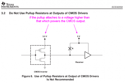
Pullup_Rs_at_CMOS_OP-NO!.png [ 32.06 KiB | Viewed 1011 times ]


FWIW, let's look at the situation where there are NOT two different supply voltages involved (ie, if both devices are powered by the same voltage).

At the risk of stating the obvious, the pullup will hardly make any difference, because the totem-pole output will pull to the rail anyway. Although the pullup does appear in parallel with the upper FET, the FET's On Resistance is likely to be far lower than the resistance of the pullup, making the latter pointless.

-- Jeff

_________________
In 1988 my 65C02 got six new registers and 44 new full-speed instructions!
https://laughtonelectronics.com/Arcana/ ... mmary.html


Top
 Profile  
Reply with quote  
 Post subject: Re: CMOS compatible SRAM
PostPosted: Sat Aug 26, 2023 2:04 pm 
Offline

Joined: Thu Dec 26, 2002 12:29 pm
Posts: 51
Location: Occitanie, France
... unless they are maybe implying that internally their TTL compatible CMOS is actually internally powered through an LDO as was surmised above.
NYWAY, I'm reassured that it has a reasonable chance to work, so I'm moving-on to other potential gotchas in my design. Thanks all.

_________________
Glenn-in-France


Top
 Profile  
Reply with quote  
 Post subject: Re: CMOS compatible SRAM
PostPosted: Sun Aug 27, 2023 5:45 pm 
Offline

Joined: Mon May 21, 2018 8:09 pm
Posts: 1462
One sensible way of converting a TTL signal to a CMOS one is to insert a jellybean buffer, either of the 74AHCT family (which has TTL compatible inputs and CMOS outputs) or a 74AHC family Schmitt trigger (for which the inputs will be TTL compatible). The 74HCT and 74HC families can also be used if you don't need the speed of the AHC logic.

On a bidirectional bus you'll need to be careful to use tristate buffers, and switch off the outputs whenever a conflicting drive may be present.

Also note that Vih and Voh of CMOS-3.3V logic is pretty close to TTL and will likely be compatible. That might be a good reason in itself to go for a 3.3V design.


Top
 Profile  
Reply with quote  
Display posts from previous:  Sort by  
Post new topic Reply to topic  [ 18 posts ]  Go to page Previous  1, 2

All times are UTC


Who is online

Users browsing this forum: No registered users and 10 guests


You cannot post new topics in this forum
You cannot reply to topics in this forum
You cannot edit your posts in this forum
You cannot delete your posts in this forum
You cannot post attachments in this forum

Search for:
Jump to: