gfoot wrote:
According to the datasheet though, that oscillator is for 3.3V operation, not 5V - is that definitely the part you're using?
Well sh**.

I could have sworn I had applied the 5V filter to both my Mouser / Digikey searches.

That being said, the 25.175MHz oscillator I used to test is the one from the VGA circuit; it's definitely the right voltage, and it gives me the same kind of intermittent behavior.
Quote:
Paganini wrote:
The clock signal looks good at the CPU... when it's there at all!
Oh so sometimes you don't see the clock signal at the CPU? At least there's something clear missing then!
Sometimes I don't see it at the oscillator.

Quote:
This might be a silly question, but you have checked that the smaller socket's VCC pin is actually providing power? You could also connect an oscilloscope to it set to trigger on an edge at e.g. 4V, and see if it ever triggers, to see whether you're getting an intermittent connection.
I checked with my multimeter before populating the board that every ground pin and every VCC pin had continuity with ground and VCC. I also powered the board and checked for 5V between each socket's VCC and ground. Maybe connections that are good enough to satisfy my multimeter are not good enough to satisfy an IC? Also, I'm not sure my old analog scope can trigger on a specific voltage; if it can I don't know how to do it!
One thing, though, is that even when the oscillator is working and I get a clear clock I still get intermittent functionality. Right now I have the board sitting next to me with the 25.175MHz full can installed. I can see on the scope that the clock is working, and the stretcher is working (which means the RAM/ROM decode is working) but it's still only able to initialize the VIA if I apply pressure to the board.
Quote:
Quote:
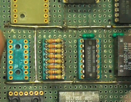
The ground network is a grid of bare wire on the component side of the board. It's a one square per IC resolution.
Oh wow, that's very thorough. My breadboard ground grid is just the regular ground rails plus three or four "vertical" connections between each pair of adjacent rails.
I was inspired by one of Bill Herd's boards:
https://hackaday.com/wp-content/uploads ... header.png And also by Jeff's inspirational lecture which proved to be the difference between working and not working for one of my earlier breadboard projects!
Quote:
Quote:
Quote:
Also, did you connect the fourth pin of the oscillator? Sometimes this is an "enable" pin. If it's floating maybe that's why it's erratic and likes having your finger there.
I didn't connect that pin; the 27MHz can I have is this one, which I think is one of the pin 1 = NC ones:
https://www.digikey.com/en/products/det ... -EK/675389Hmm, I always connect it just in case.
What do you connect it to? On the cans that have tri-state, are the enable signals always active high (or low)?


