6502.org Forum  Projects  Code  Documents  Tools  Forum
It is currently Sat Apr 27, 2024 7:26 pm

All times are UTC


Post new topic Reply to topic  [ 17 posts ]  Go to page 1, 2  Next
Author Message
PostPosted: Tue Jun 20, 2023 9:57 pm 
Offline
User avatar

Joined: Sat Jul 24, 2021 1:37 pm
Posts: 282
Hi all,

I recently wanted to use Atmel's line of CPLDs, namely the ATF1504 and ATF1508 in PLCC 44 and 84 respectively. In order to experiment with those chips on a breadboard, a small adapter PCB is needed. I'm sure it has been done already, but it was a fun little project!

My goal was to use a slim "stick" format, with the CPLD hanging off to the side. This allows easy access to the pins of the device by keeping accessible two rows of holes on each side of the breadboard. In order to keep costs low because this is just an experiment, I went for a 2-layer design, assuming a breadboard will have poor signal integrity and grounding anyway. Additionally, I took care to group pins from each logic block, so it is easy to hook up related signals in an efficient way. I also added an option for local decoupling with SMD caps on the back.

Fanning out the PLCC-84 this way was a *significant* challenge, so I'm quite happy to have made it (It goes from 25€ to 5€ with two layers!).

I hope this is interesting to someone! Source is available on my GitHub, and gerbers are attached below for posterity.

https://github.com/adrienkohlbecker/atf ... 4_breakout

Note: At the moment I have not actually built these, they are still on order. I will report back if I find any issues!

Attachment:
board-1.png
board-1.png [ 597.17 KiB | Viewed 53598 times ]

Attachment:
board-2.png
board-2.png [ 690.14 KiB | Viewed 53598 times ]

Attachment:
board-1.png
board-1.png [ 446.78 KiB | Viewed 53598 times ]

Attachment:
board-2.png
board-2.png [ 463.67 KiB | Viewed 53598 times ]


Attachments:
atf1504_plcc44_breakout-RevB.zip [47.02 KiB]
Downloaded 80 times
atf1508_plcc84_breakout-RevB.zip [67.17 KiB]
Downloaded 71 times

_________________
BB816 Computer YouTube series


Last edited by akohlbecker on Sat Jul 15, 2023 9:28 pm, edited 3 times in total.
Top
 Profile  
Reply with quote  
PostPosted: Wed Jun 21, 2023 5:38 am 
Offline
User avatar

Joined: Tue Feb 28, 2023 11:39 pm
Posts: 133
Location: Texas
Let me know how this goes. I'd love some break out boards for these guys.

I currently have a bunch of 1502's that I haven't gotten a chance to use yet because I don't have any way to plug them in and program them. >_<


Top
 Profile  
Reply with quote  
PostPosted: Wed Jun 21, 2023 1:03 pm 
Offline

Joined: Sun May 13, 2018 5:49 pm
Posts: 247
I'm also interested, as I have a couple of these CPLDs (EPM7128S, in my case) kicking around that I haven't done anything with yet. Let us know how it goes.


Top
 Profile  
Reply with quote  
PostPosted: Thu Jun 22, 2023 12:16 pm 
Offline
User avatar

Joined: Sat Jul 24, 2021 1:37 pm
Posts: 282
Last minute update to the design before finalizing my order: I added a spot for an optional clock oscillator connected to the first global clock input (GCLK1, 7.5x5.0mm SMD), to help generate high frequency signals such as video pixel clocks. And a spot for a bulk decoupling electrolytic.

_________________
BB816 Computer YouTube series


Last edited by akohlbecker on Mon Jul 03, 2023 7:28 pm, edited 1 time in total.

Top
 Profile  
Reply with quote  
PostPosted: Mon Jul 03, 2023 3:30 pm 
Offline
User avatar

Joined: Sat Jul 24, 2021 1:37 pm
Posts: 282
Boards are still in shipping. I've been looking at oscillators for the projects I intend to build on this, and I'm disappointed by availability and price, so I kind of regret adding that last minute footprint.

Consequently, I'm working on a second revision of the 1508 board, with a bunch of new features:
- Footprint for a DS1086 programmable clock generator to use clocks from 260kHz to 133MHz. I tested this IC recently and I've been really impressed by it. It is super flexible and with a price comparable to some of the can oscillators you have to buy. This should give the power to work on any type of synchronous design.
- Footprint for a DS1813 to provide a de-bounced push button input and power-on reset, connected to GCLR.
- Power LED, as well as a User LED connected to pin A4.
- Optional pull-up/down resistors on the JTAG lines (in case the built-in ones are not enabled for some reason).

Here is a preview, I'll post the production files once I've tested revA. As you can see, the board in this form factor is super dense :mrgreen:

Feedback welcome!

Attachment:
Screenshot 2023-07-03 at 17.27.08.png
Screenshot 2023-07-03 at 17.27.08.png [ 1001.33 KiB | Viewed 53862 times ]


Attachment:
Screenshot 2023-07-03 at 17.18.13.png
Screenshot 2023-07-03 at 17.18.13.png [ 613.22 KiB | Viewed 53862 times ]


Attachment:
Screenshot 2023-07-03 at 17.18.22.png
Screenshot 2023-07-03 at 17.18.22.png [ 731.76 KiB | Viewed 53862 times ]


Attachment:
Screenshot 2023-07-03 at 17.17.55.png
Screenshot 2023-07-03 at 17.17.55.png [ 666.91 KiB | Viewed 53862 times ]

_________________
BB816 Computer YouTube series


Top
 Profile  
Reply with quote  
PostPosted: Wed Jul 05, 2023 1:03 pm 
Offline
User avatar

Joined: Sat Jul 24, 2021 1:37 pm
Posts: 282
Boards have arrived! I'm pretty happy with the form factor and integration into a breadboard. The silkscreen pinout is really nice to have for experimentation. I'll assemble them soon

In the same batch, I also designed breakout boards for FTDI's FT4232H Mini Module (4 channel USB-to-UART/JTAG/SPI/I2C development board), as well as the 65C816 and 65C22 in PLCC-44 format (because I only had PLCC versions in stock and it seemed silly to purchase DIPs if I could design this adapter for a couple euros).

Attachment:
IMG_9887.jpeg
IMG_9887.jpeg [ 3.51 MiB | Viewed 53799 times ]

Attachment:
IMG_9888.jpeg
IMG_9888.jpeg [ 3.95 MiB | Viewed 53799 times ]

_________________
BB816 Computer YouTube series


Top
 Profile  
Reply with quote  
PostPosted: Fri Jul 07, 2023 12:05 am 
Offline
User avatar

Joined: Tue Feb 28, 2023 11:39 pm
Posts: 133
Location: Texas
They look great! Love to see them after you get them soldered up and functioning.

Out of curiosity, I can never make heads or tails about what the USB of FT4232H is for. Is it just a fancy high speed serial port or can you use it as a host controller for other USB devices?


Top
 Profile  
Reply with quote  
PostPosted: Fri Jul 07, 2023 9:38 am 
Offline
User avatar

Joined: Thu Dec 11, 2008 1:28 pm
Posts: 10793
Location: England
> Out of curiosity, I can never make heads or tails about what the USB of FT4232H is for. Is it just a fancy high speed serial port or can you use it as a host controller for other USB devices?

I checked the datasheet. It's a device with a USB side and a serial interface side. The USB side acts as a peripheral so it connects to a USB host. The serial interface side includes i2c and SPI modes which are driven by the chip, so the chip is the host. Also includes UART which can be bidirectional or unidirectional. Typically you might use UART mode and connect it to the UART on your own project. Either side can then send bytes to the other, and it's up to you what protocol you build on top of that. The chip also includes some GPIOs, so the host side can control those to bit-bang some other protocol, although I would guess only slowly.

Long story short, you plug a USB cable in one end and connect to a host, probably a PC, and you connect with serial to the other end.


Top
 Profile  
Reply with quote  
PostPosted: Fri Jul 07, 2023 6:28 pm 
Offline
User avatar

Joined: Sat Jul 24, 2021 1:37 pm
Posts: 282
I've posted a bit more about how I intend to use the FT4232H here viewtopic.php?p=101299#p101299.

Boards are assembled and looking good :-) I had quite a bit of fun soldering the FTDI breakout, as it was my first 0805 components.

I'll test them soon and report back.


Attachments:
IMG_9911.jpeg
IMG_9911.jpeg [ 2.76 MiB | Viewed 53672 times ]

_________________
BB816 Computer YouTube series
Top
 Profile  
Reply with quote  
PostPosted: Sat Jul 15, 2023 8:25 pm 
Offline
User avatar

Joined: Sat Jul 24, 2021 1:37 pm
Posts: 282
I'm happy to report that both breakout boards seem to work perfectly!

As a test, I implemented the logic from my other recent post on RDY single stepping (viewtopic.php?f=4&t=7641). Here is my source code for that:

Code:
Name     singlestep ;
PartNo   00 ;
Date     15/07/2023 ;
Revision 01 ;
Designer Adrien Kohlbecker ;
Company  - ;
Assembly None ;
Location  ;
Device   f1508ispplcc84 ;

/* Enable pull ups on JTAG interface */

PROPERTY ATMEL { TDI_PULLUP = ON };
PROPERTY ATMEL { TMS_PULLUP = ON };

/* Pin and pinnode definitions */

PIN = CLK;         // CPU PHI2 Clock
PIN = SYNC;        // CPU SYNC Output
PIN = RDY;         // CPU RDY Input (Warning: use open-collector output)
PIN = STEPB;       // Step control input (low-going pulse)
PIN = HALT_RUNB;   // Enable single stepping (high), or run the CPU freely (low)
PIN = INST_CYCLEB; // Single step per instruction (high), or per clock cycle (low)
PIN = IOCLK;       // Stretched clock output

PINNODE = RDY_1;         // Internal RDY bit (needed to implement pseudo open-collector output)
PINNODE = STEP_STATE;    // Internal state storage
PINNODE = STEPB_1;       // STEPB input synced with the clock to prevent metastability (only one needed for double flopping because RDY is also registered)
PINNODE = INST_CYCLEB_1; // INST_CYCLEB input synced with the clock to prevent metastability (only one needed for double flopping because RDY is also registered)
PINNODE = HALT_RUNB_1;   // HALT_RUNB input synced with the clock to prevent metastability (1/2)
PINNODE = HALT_RUNB_2;   // HALT_RUNB input synced with the clock to prevent metastability (2/2)

/* Synchronising inputs to the clock (double-flopping) */

HALT_RUNB_1.D = HALT_RUNB;
HALT_RUNB_1.CK = CLK;
HALT_RUNB_2.D = HALT_RUNB_1;
HALT_RUNB_2.CK = CLK;

STEPB_1.D = STEPB;
STEPB_1.CK = CLK;

INST_CYCLEB_1.D = INST_CYCLEB;
INST_CYCLEB_1.CK = CLK;

/* RDY signal generation */

RDY_1.D = STEP_STATE & STEPB_1;
RDY_1.CK = CLK;
RDY_1.AP = ! HALT_RUNB_2;

/* Pseudo open-collector output, easier than adding the proper option on the command line arguments. */

RDY = 'b'0;
RDY.OE = ! RDY_1;

/* Internal state store */

STEP_STATE.AP = !(STEPB_1 # STEP_STATE);
STEP_STATE.AR = !(!RDY # INST_CYCLEB_1);
STEP_STATE.CK = SYNC;
STEP_STATE.D = 'b'0;
 
/* Output clock streched with RDY (stays high as long as RDY is low) */

IOCLK = CLK # !RDY;


I then programmed both an ATF1504 and an ATF1508, using ATMISP and the official ATDH1150USB, and built a testing setup using push buttons, DIP switches and LEDs. The CPLDs were happily programmed and the logic seem to work as it should.

Attachment:
IMG_9991.jpeg
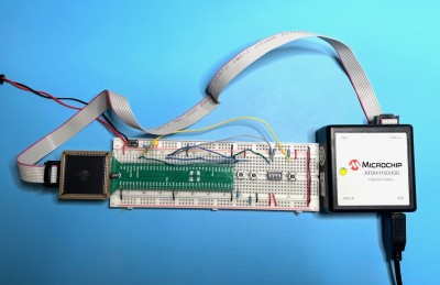
IMG_9991.jpeg [ 443.57 KiB | Viewed 53607 times ]

Attachment:
IMG_9990.jpeg
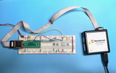
IMG_9990.jpeg [ 446.95 KiB | Viewed 53607 times ]


As for a second revision of the boards, that project has kind of turned into a full-featured development board PCB including 12V programming, programmable clock, reset signal, etc. I plan on keeping the breakout board design shown here for quick and dirty projects, as the new version will include a lot of more advanced circuitry which is not always needed. More details to come in another post.

_________________
BB816 Computer YouTube series


Top
 Profile  
Reply with quote  
PostPosted: Sat Jul 15, 2023 9:29 pm 
Offline
User avatar

Joined: Sat Jul 24, 2021 1:37 pm
Posts: 282
I've made a minor revision B which adds pin number legends for the global inputs, as it makes reading the fitter output easier. I also had to re-order them to make the new silkscreen fit. Top post updated with new gerbers!

_________________
BB816 Computer YouTube series


Last edited by akohlbecker on Sat Jul 15, 2023 9:35 pm, edited 1 time in total.

Top
 Profile  
Reply with quote  
PostPosted: Sat Jul 15, 2023 9:30 pm 
Offline

Joined: Fri Dec 21, 2018 1:05 am
Posts: 1076
Location: Albuquerque NM USA
Looking great!
They should also work with Altera EPM7000S parts. ATF1508 is same as EPM7128SLC84; ATF1504 is same as EPM7064SLC44.
Bill


Top
 Profile  
Reply with quote  
PostPosted: Wed Sep 27, 2023 3:00 pm 
Offline

Joined: Wed Sep 27, 2023 2:46 pm
Posts: 2
Hi, those look like fantastic well designed little PLCC adaptor boards!

Coincidentally, I have just been looking at these ATF150xx series of CPLD’s as a follow on to the more basic ATF22V10’s and was considering experimenting with them too . It seems I’ll need to purchase the official microchip cable to program them as indeed you have done. I’m really pleased you’ve posted your efforts on here. I’ve enjoyed watching your 65816 YouTube series, will you be posting a video on your work with the ATF1504 and ATF1508? I do hope so!

Keep up the excellent work! :D


Top
 Profile  
Reply with quote  
PostPosted: Wed Sep 27, 2023 3:16 pm 
Offline
User avatar

Joined: Sat Jul 24, 2021 1:37 pm
Posts: 282
Thanks a lot for the kind words.

You may be able to use a FTDI USB chip if you already have one and skip the official programmer. There is a schematic here https://www.hackup.net/2020/01/erasing- ... 1504-cpld/ that I have not personally tested yet.

The programmer is basically a FT2232D. See teardown http://www.bytecruft.com/2012/04/atdh11 ... -down.html and possibly schematic (not verified by me) https://github.com/programmable-logic-t ... tdh1150usb

_________________
BB816 Computer YouTube series


Top
 Profile  
Reply with quote  
PostPosted: Wed Sep 27, 2023 4:06 pm 
Offline

Joined: Wed Sep 27, 2023 2:46 pm
Posts: 2
Hi Again,

Too late! I’ve just ordered the official ATDH1150USB-K direct from the manufacturer Kanda, they seem to be the cheapest option that I could see for the genuine programmer.

Thanks for the links to the alternative FTDI USB options though.

Now I just need some free time to experiment!


Top
 Profile  
Reply with quote  
Display posts from previous:  Sort by  
Post new topic Reply to topic  [ 17 posts ]  Go to page 1, 2  Next

All times are UTC


Who is online

Users browsing this forum: Google [Bot] and 29 guests


You cannot post new topics in this forum
You cannot reply to topics in this forum
You cannot edit your posts in this forum
You cannot delete your posts in this forum
You cannot post attachments in this forum

Search for:
Jump to: