... with graphics pixel blitters.
This is kind of my response to the graphics ideas in the
24bit parallel colour data to HDMI thread. Especially Proxy's post on multi-MPU systems:
Proxy wrote:
while writing this i thought more about the network idea, and how modern GPUs have so many cores that each of them can take care of a small set of pixels.
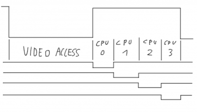
so, what if you had more than 2 CPUs? 4x 65C02's for example that all share the same fast single port SRAM with a video circuit. a lot of graphic operations can be split into multiple smaller pieces (like scrolling or drawing shapes).
my idea of connecting them was to have all CPUs run on the same clock with the same phase. but then use extra logic to restrict their time on the bus when PHI2 is high.
Attachment:
 gimp-2.10_woQn9hkGhn.png [ 29.61 KiB | Viewed 928 times ]
using bus tranceivers and latches (latches because data is only read on the falling edge of PHI2, so the data needs to be stored), each CPU could get a small part of PHI2=High time without having the CPUs themself run at extreme speeds. but of course the more there is on the bus the faster the support logic needs to run, which comes dangerously close to FPGA territory.
anyways, overall i still think that for these kinds of graphical goals you likely won't get something useable without either progammable logic, a crazy setup like the multicore bus sharing, or both!
i still wish you luck with whatever you might have planned, and i'm eager to see it work!
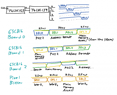
The major difference between Proxy's diagram and mine (if I've understood correctly) is that I stagger the PHI2 clock signal to each '816 and instead of having a specific video access period I have a memory access window where none of the '816s are accessing memory.
Attachment:
 Timing.png [ 39.19 KiB | Viewed 928 times ]
Think of the yellow signal as being a memory access window. The first
65C816 Board's memory address and data are kept of the main memory bus until time SEL3 where a read or write from main memory can be done.
Similarly
65C816 Board 2 is kept off the main memory bus until time SEL0 where a read or write from main memory can be done.
The blue line indicating PHI2 for each board is asymmetric with PHI2 being low for only 25ns and then high for 75ns. This is done so that there are 50ns to do address decoding and to ensure that the address lines are stable before the memory access in the last 25ns happens. For those wondering the result of a read is latched so that it can continue to be presented to the '816 after the memory access window closes.
Fundamentally this is all there is to it. Any device can do anything it wants as long as it understands it only has a 25ns window in which it can access the main shared memory bus.
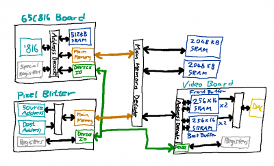
That main memory bus includes the video device. The thing that actually produces a pretty video signal.
Attachment:
 Sorta Block Diagram.png [ 30.4 KiB | Viewed 928 times ]
If the Pixel Blitter is given its own memory access window then it can use that to read from main memory during one access and write into video memory during a second access. Or read from video memory or write into main memory or any other combination. The video back buffer is just addresses on the main memory bus.
(In the picture above I should have labelled 'Address Decode' as 'Address Bus' and 'Main Memory Decode' as 'Main Memory Bus'.)But now we can get a bit more involved. The Pixel Blitter and the
65C816 Board can share a memory access window provided that they never both try to use it at the same time. That means that whilst the '816 is doing stuff the Pixel Blitter must be disconnected from the main memory bus.
And that means the the '816 cannot access the main memory bus whilst the Pixel Blitter is doing things.
(Remember this is only for shared memory access windows. If the '816 is using one memory access window and the Pixel Blitter another then that's fine. They can both run in parallel).Deny a running '816 access to memory is considered bad form and leads to unhappiness. And that is why each
65C816 Board also has its own private memory. The 512KB SRAM in the diagram. In fact the device access that drives the Pixel Blitter (or any device) can only happen when the '816 is running against private memory. That private memory mode - called
Kernal Mode - is accessed by interrupt. Either a software or hardware interrupt. When the '816 runs user programs in main memory - that I've called
User Mode. The '816 returns to user mode after an RTI has been called for every interrupt that's currently counted. (Bit of a side design digression there.)
Attachment:
 Bigger Block Diagram.png [ 29.14 KiB | Viewed 928 times ]
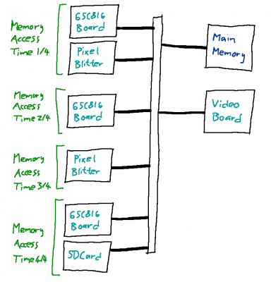
Putting it all together we can now have multiple devices in a memory access window provided that only one ever accesses memory during that window. And there can be multiple devices* running in parallel in separate memory access windows.
And that is how I'm planning on generating 60FPS in a high resolution of 400x300 at 8bpp

. Or lower, but usable, frame rates in 800x600.
* This includes an SD card device running in SD mode doing very, very fast block transfers into and out of main memory. That's why there's an SD card on the main memory bus too.


