several people have advised me to 'start small' and 'get an MVP going'. who am I to argue?
while having other, more complex and auspicious goals and projects are good,
'cutting stone' is often done before a foundation is placed.
I am working on a small 65c02 device that will use the Oxide OS in runlevel -0 or -1.
Chronos(working title)
The "Chronos" will use a 4-way Directional Pad (D-Pad) and standard input buttons, currently called "yes", "no", "menu" and uh "option" or whatever, red, purple, blue and pink. a byte of input to be polled or irq on change maybe. Im not sure yet. 8-bit controller input.
The Chronos has a 6502, a tiny bit of RAM and a tiny bit of ROM.
The ROM is probably 1-2K at most. possibly far, far less depending on iteration.
The Chronos by default uses banks of 8 LEDs to represent contents of the Flag register, and the "Display" register, which is basically just copied from the Accumulator on update.
Further iterations may use multiple Display Registers, such as A, X and Y, or even a full 8x8 grid, or other arrangement may be explored, it is possible that a version of Chronos may exist with an LCD screen, however this along with an 8x8 register bank are beyond the current scope of this project.
Operation.
Chronos uses the accumulator and various opcodes to perform binary computation directed by the user.
Input Commands:
Up: add 1 to accumulator
Down: subtract 1 from accumulator
Right: binary shift right (this will probably use the Rotate with Carry to utilize the Flag register and 'wrap around')
Left: binary shift left (this will probably use the Rotate with Carry to utilize the Flag register and 'wrap around')
Menu: Reset all Variables
Option: Store Accumulator in M+ location (possibly the stack)
Yes: Binary AND with M+ (or some other operation)
No: Clear ACC to zero
As the project grows and ideas become realized, it is possible to get this to perform actual work, using the Yes/No or "Confirm/Back" buttons to enter or back out of a register, you could move up and down to A, X or Y registers, possibly expose the top of the stack next to the Flag register, or have a small grid of banks to use for maths. you would select a bank by moving the select LED to the bank, selecting that bank so its 'active', using the dpad and buttons to set its value, and then you could perform a set of booleans, AND, OR, XOR, NOT, and get the out put of those in your ACC (or wherever).
While trivial, so are most pocket calculators and plenty of those get made. I think this is a good spot to aim for in hardware, software and functionality. This could possibly be used as a 'learn to solder' style of instructional kit, and if actually made into something helpful, useful and practical. Im not sure about al of that, it does get a cpu on a breadboard and blinks LEDS and importantly, exposes the computational logic to the user as directly as possible.
The device might single step, it will probably run a 32.768 Khz (or 3.2768 Mhz?) and have a real-time clock of some sort. Might BCD for that? Or just have a binary clock of some kind. The point is, this breadboard computer, will have functionality and use beyond mere construction and will offer building blocks to other projects in the future.
This is inherently one of the most useless things I could create; however, it should pick up where a lot of the 'build a computer' stuff leaves off, and might actually be useful at some point to teach or perform quick binary math ops.
I started on a schematic, though I need to head out for the day. Im pretty sure I want to use some Latches in here and there is a lot of other little stuff I am missing. I was not planning to use a 6522 for this, I think its probably overkill.
all the passives, all the little things, a counter for the clock to become a Real Time Clock, stuff like that.
still, its a computer with a 6502 in it.
Attachment:
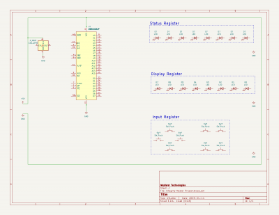 CompuCalc.png [ 71.59 KiB | Viewed 1155 times ]
__________________________________________________________________________________
DevLog
4.16.23.1.40.pm
it is really hard to suppress my design side and add a million features and make a ti voyage 200... wait I do kinda want to do that...
I have been in "analysis" (ADDIE: analysis, design, develop, implement, evaluate) mode and I am collecting a few places people thought might be helpful, like binary to bcd conversions and having the stack exposed or some form of polish notation.
banks of LEDs are great for proof of concept, its not going to last very long before I move on to something bigger. planning ahead is a good way to organize. so eventually, Im going to want a display of some kind. some dot matrix or 7-segment stuff might be good.
for the life of me, everything wants RAM in SPI or whatever and this make zero sense to me, to serialize RAM and then deserialize it for the cpu..?
I wanted to grab 2Kbit (256 bytes) in some nice fast SRAM to put right up next to the 6502 for its zero page, you cannot get parallel access RAM this way o.O
considering a 6522, and a screen, and more buttons, and a port and its "the Integrity in 8-bit with a b&w screen" :/
that might be okay to develop, though a 'power calc' I think might do better for what Im after.
gameboy with a number-pad? thats a nice calculator, its never going to "beat" a ti-83
so, for soldering practice, building a simple device to learn a few things might be fun, and having that 'do computer maths' is pretty cool, and Im planning to use a Real-Time clock module in there, so yes, the first experiments are in blinking LEDs directly with the CPU, the next, I think might start getting to be an actual calculator
__________________________________________________________________________________
4.17.23.8.28.am
feature creep again, there are two project here, one is an LED blinker to break the ice and tinker, the steps needed to display, manipulate and compare or combine two registers, is a program loop, running, it is the seed of an OS or computer. this is the first part, and it is not hard, well documented and I will learn a little. it is only one incremental step towards the Integrity. while the Integrity is basically my dream device, its an errand of adoration. the Integrity is a full color, penabled, expandable device with maximum RAM and a full array of multimedia chips. Chronos cannot be this. It should not be 'the Integrity lite' (or should it be).
I am considering Display Options for the Chronos .
Flag Register Mirror
Accumulator Mirror
X Mirror, Y Mirror
Top of Stack Mirror
Counter/Clock Mirror?
thats about 5 banks of LEDs, and certainly doable, in fact, you could use a 4x16/4x20 dot matrix.
Id even use different colors of LEDs, and add an extra one for 'selected' or 'active'
you are never going to do much with this other than demonstrate very slowly what is going on in the mpu. this is a worthy educational goal and suitable for soldering practice. however, it is not practical for daily use. In getting this running we are going to get som core loops and ASM routines implemented and gain the basis of Runlevel 0, perhaps some kind of sensor set that reverses direction controlled by the CPU? that would be a great "Headless" application, a motor stopper. So have a motor and controller on a board move a 'car' and if it hits a switch, the cpu gets an interrupt, stops the car and sends the reverse direction command to it, until it hits the other end... i might fake that in LED chasers for simplicity, however, that is the basics of a headless application. Beyond this, 3d printers, plotters, pick and place machines etc are all the next set of "headless" OS applications and are largely out of the scope of the Chronos project space.
so, really if you want more than a digital fidget toy with LEDs on a keychain, Chronos needs to probably have a screen.
7 segment displaystraditional or lcd calculator/watch style.
we are building a pocketwatch/calculator style device? (Id like one of these)
7-segment displays are cool, you can do Hex on them and greatly simplify the display space.
turning one sideways like an infinity symbol covers the 6502 flag (status) register as it only uses 7 bits.
This will create an alien calculator only the truly initiated can use; especially once you start doing binary ops.
I might build one of these just because. get some different colored digit pairs for different 'registers'. as you can display 8 bits on a 7-segment display, or use hexadecimal for two characters per byte instead because its easier to read... then you get the BCD in multiple display modes...
Its really fun to think about the ways you could expose a 6502 to the user as a calculator and have various routines you could run on a programmable calculator with a 6502 in it...
however, i do not find this practical for use beyond novelty and edge use cases.
watch style LCD display.you have several options here including calculators, time, battery indicators etc, however, it gets very expensive very quickly.
these and new e-ink displays of the same type might offer a nice 'extra screen' or external status display, such as clock/timer, battery level and possibly some basic calculator functions or other indicators. you are very locked in to the manufacturer's design.
cost wise, unless you aim for a very low end watch display (which does give you several 7-segment displays you can use to show registers) it is far more practical to get an actual display
LCD screenB&W or monochrome screens are available in 'graphing calculator' resolutions and are very affordable under $20 single unit cost.
however, again, once you hit a certain point to get anything resembling a useful resolution you might as well get a 'regular lcd'.
getting a 'low color space' or grayscale screen is difficult but not impossible. you can get ti-83 to gameboy resolution here with better color depth. screen size and resolution here are a concern as I would prefer to develop for as few modes as possible right now.
again, once you break $20, you are entering full color screens and 400x240 resolution, which exceeds to Ti-voyager 200 or ti-92, which is quickly becoming the form factor we are approaching. I did always want to make one of those, like a voyager version of the n-spire...
ok, so perhaps there are some options here for screens. in the meantime, Ill stick with the 160x96 module I found for under $15 thats 1/5th 800x480 and uses a standard documented controller, it has greyscale, so we are better than a ti-83 here and just shy of a gameboy with more shades of grey. Its at least going in the prototype. 160x100 is more common, and uses a 'tile row' with only 4 pixel rows used, so thats 'kinda compatible' and more ubiquitous. So, LEDs and 'nixie' blocks for the proof of concept, and then go with a screen of some kind. the one mentioned is fairly large with low resolution. something bigger than 3" across so its readable, and this is where cost is a balancing act with desired display sizes.
several module are under $45 and have a built in
https://www.displayfuture.com/Display/d ... T7796s.pdf ST7796s or similar. these will run on the 8080 8-bit protocol (or 3 others) or SPI. a nice 4.3" color screen would make a $100 programmable graphing calculator with a few options. It is a watered down Integrity at that point. so simplifying leads to other options.
I think an okay screen for under $25 is ideal, if I could get something the right size...
the screen is a huge determinant in form factor. I see two devices emerging from this experiment, a device a bit bigger than your phone, a graphing calculator with some options, maybe a PC Card slot. its going to have a lot of value for its cost. it will not be a full blow Integrity penabled speech synthesizing tablet with an 8.4" screen at 480x800. It will have a 4.3-5.5" screen, at 240x400. It will not have a big GPU or sound card. It might have a GPS and or radio, probably to receive weather band. It will have a 64-bit (probably unless trying to use it with a 6502 is too much overhead and the 32 works better) math coprocessor, it will have a few nice features and may never exist, because the work to build it, is as much as the integrity. maybe Ill just make a nice calculator.
the other is a portable device, its like a clamshell gameboy advance, the SP., it had a ~3" screen at 240x160, so we will be exceeding that only slightly, it has our input setup, a compass, music player, gps, weather radio, possible distress beacon, is hardened and it can play a few games and do math, it will have the OS 'monitor' and maybe some calculator software you could use a little.
I think I can build that for well under $100, though Im not sure if I can make it 'hardened'
InputI still want to stick to the classic "8-bit" controller, however, adding a number pad and keys or calculator pad is a really good idea.
this input should be memory mapped to a specific memory address (with a couple of extra bytes above it) and it should always just be readable by the cpu as 'last input polled'. no matter where or how that register gets set, by the cpu or other chips, it should just be there, so if an IRQ for the gamepad comes in, al it needs to do is read that location, input queueing might come later, by design, the 'OS' just needs to read address $DC4B or whatever, and there is the bit-mask for the input from the dpad and its 4 buttons, and this should be in the core loop I think. I was going to run a main loop like you do for games and include an input update section in it. so a software interrupt can say 'go do the OS routine' or such and the input, sound, display and I/O all get at least checked for errors.
I do not think I want a QWERTY KB on this device, rather an onscreen or attachable KB is better. Its a watch/calculator/gameboy.
a clamshell design is a notion as is a book/bar type. I like a set of keys under the screen between the normal input. getting a board for a keyboard with a gamepad is really easy they make controllers with keypads on them, so that is something to explore.
I think qwerty is 'too much' and a good set of calculator keys is the way to go, maybe with the Hex digits. lots of math symbols like pi.
Other chipsSo a 6522 is starting to look likely, once we get past blinking LEDs and want to do anything useful. I do want to demonstrate and that you can use a 6502 'directly' to do math at human speeds. Beyond this however, if you are going to have more than a clock or alien math fidget stick, you need some hardware. with a possible screen or more complex display, a 6522 is an obvious choice, especially once you add in a keyboard. So, if it is a calculator, then using a math coprocessor is only a few extra bucks and rather 'worth adding' in addition to those lookup tables. one does not preclude using the other. the micromega uses I2C or SPI, and several other possible chips use SPI, which is not difficult to do with the 6522 from what I have read. So this is starting to look more and more like that 'Core' or RED zone for the integrity, with a 6502 instead of a 65816, and no DART unit yet. some RAM and ROM. I wanted to put 2Kbit of SRAM at zero page, though its hard to get that these days in anything except SPI... SPI for ram.. wth? its probably for a battery backed solution of some sort. SPI for RAM, makes very little sense to me, especially for something like zero page, I want to use as 'cache RAM'.
Getting a bigger RAM chip is fine, I do need to make room for the ROM and I/O devices. for the Math coprocessor, sure, you are going to use it for its big number and advanced functions. its 64 bit, unless I opt for the 32bit version (idk, its only $3 less)
a bunch of stuff wants a 32.768kHz clock. so thats going to be a thing. 2,3, 4 different chips so far, FPU, the MAX real time clock/calendar chip thats less than $3 and gives a full PDA worth of functions through 2399 or whatever. Ill review a few other chips, having a nice clock with stop watch is nice. I know you can maker one with a 6522, though I figure I want one anyway. if I could find one with a few more timers or such, multiple alarms for $1 more I might to save writing software. So, a 6502, and a 6522, and a &32k clock, and a real-time clock chip. we are getting close to a computer here. if the 6551 was not bugged I might add it, as is Im not certain this device needs a UART or 'DART' unit. kinda... when it comes to a clock, everything 'wants' a 32.768kHz crystal or clock signal. the max chip prefers a crystal with capacitors. Personally, I want millisecond precision. Time stretching and single stepping the CPU/system clock is great, however, somewhere in there, I want milliseconds, and that means, well, 32.768 MHz, or with margin of error, about 33Mhz... that number does seem to pop up here and there on some busses... I think running the GPU at 3.2768 MHz, or an independent frequency from the clock is probably ok, however, that is probably an okay speed to run the bus at, so perhaps some multiple there off might work, or we can decouple the buss from the real time 'low speed' oscillator and use sensible numbers on the bus. Again, we have now stepped into the "Integrity Lite" territory, however I think this device, which we cannot call the Chronos , does have merit.
a dedicated linear compass IC is a buck fifty. I want one of those in my watch thank you. which might spin its own project, a pocket watch and compass. it might not have a cpu...
The micromega does GPS stuff. I can get a GPS/Galileo/GNSS chip for under $10. now the Chronos might be useful for hikers or sailors too. thats worth $10 on the device, to have GPS. it might end up in a module, like a PC-Card maybe. If you did have one, then having the Chronos do nautical or aeronatical calculations might be really helpful and get some users. Im all for Open Hardware here, if people want to build a Chronos , and use it in stead of a Ti-8x in their country, that might be ok. Im pretty close to that $80-100 mark on materials right now, though several things are optional, I could get that BoM to $50 or less, and if I did make 'thousands' of them, they would at this point be competitive with a ti-83, a better screen, and a GPS. this is the advantage of our current hardware and in designing new things with decades of options, this is also the advantage of the 65xx.
Im not sure if this needs a PCMCIA controller, its going to maybe need a board controller if it does, though that opens up quite a bit for things, if I do not use the GPS, we drop $10, and its way less useful. it does not need to be a phone. maybe a distress beacon?
adding a single PCMCIA socket is going to add $15-20 for the end connector, and the body would build the rails. Ti PCMCIA bus controller is only $5-10 and offers a wealth of expandability in type-I cards.
there is an alternative to let device 'be' a PCMCIA card, and use a ribbon or connector or such. otherwise, I am uncertain it is viable to include on this device, perhaps just an RS-232 port, USB or such. a USB is certainly acceptable, as several chips include charging from usb built in.
I am thinking there may be a 'couple' of devices here, a pocketwatch/compass that might play games and compute, and a scientific calculator. the Integrity is a book sized device, it doesnt fit in a pocket, these would. a gps/weatherband compass might be nice.
so, I'll end up at least blinking LEDs, probably making a low end game boy on a breadboard. commercially, unless I hit a niche use (which gets way easier with the FPU installed and maybe a GPS) Im not sure this is very 'marketable' though Ill try.
Making the PathSolver or Chronos or Wayfinder, might be a really nice way to get a ruggedized device for hikers, fishermen, foresters etc... if I do put a PCMCIA port, it can have add-ons like a GPS, or laser rangefiner/level/ruler. Or a gyroscope, or camera. ok, and so maybe its a 'Wayfinder' or such.
Maybe a clamshell, with outer display, and a watch/clock/timer/battery meter and ideally, a solar panel.
Attachment:
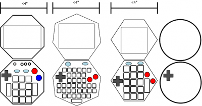 Diagram4.png [ 48.79 KiB | Viewed 1072 times ]
__________________________________________________________________________________
so there is actually a possible 'calculator' here in one form or another.
making a cool graphing calculator, that you can program, use for all kinds of math, run a few apps and has a good clock is alright.
devlog 4.20.10.49.pm
so I have been looking around and I think I have an MVP.
a 6502, with a screen, ram/rom and speaker, a few buttons and a PCMCIA basic type-I port,
this allows the "Chronos" (chronometer, chronostar, chronofinder, idk) to be a lot of different things and solves a lot of problems, want a multimeter, ok drop in a card, want a gps and trail or kayak computer, ok add a card, want games, ok, use a CF card. thoughts include a laser range finder, gps, sensor, camera etc.
basically at this point. I want to get back to the basics and I think a basic watch is a good start. like a smartwatch pocket watch, not a phone, phones are not really 'this'. I have a tape measure on my belt as much as anything. this doesnt 'need service'. it has a USB port, like a real one maybe. its a 6502, and a really good clock IC. it will have an ok screen, maybe a gpu. it should play mps etc.
so for early goals getting it to interface with a common clock is a good idea, several use parallel addressing and some include RAM with the clock mapped to top of I/O space. having zero page, or even 32K of RAM, as battery backed NVRAM or SRAM, with the clock already mapped into $FFFF8 is fine by me. Couple of other functions there, though I am looking at something with an extrernal clocl that can handle milliseconds. I guess it would not be difficult to sort out in code or on a CPLD or in logic, most clocks have 100th of a second precision and I really want that 0.001
idk why, just, status. I saw a few clocks that can do that too, so if I run at a higher clock it may be possible to get a signal for that.
some kind of inexpensive sound generator.
I am greatly considering an STM8, which is a 6502 knockoff, or an 8051 (I think it can handle ISA?)
so. basically we are taking a PC card, wrapping it in a case that has a screen and controls with a 6502 and some RAM the chips to make that work with a great real time clock.
___________________________________________________________________________________________________
devlog: 4.23.23.11.04.am
still looking at ways to get down to an MVP, to reduce the complexity, the cost, the involvement everything, how to get it down to 'as simple as possible'.
ok, so an Altoid's Mint Can, the full size one, is usually just a few dollars and will hold a credit card or business card ok. so, that means business card PC.
I think I can fit a 6502, a RAM with RTC, a 2.8" or so 320x240 color LCD, some registers or a 6522, support hardware etc in this space, I believe I saw a business card PC on the SBC- area of the site.
this suggests an even more simple design that the Chronos, which is a pretty maximized 6502 system that can probably take expansion cards and a GPS. the Chronos is meant to be used on jobsites, where you would not use a motorola Z-Fold. its the size of a tape measure and might have a good level and compass. It will do carpenter math better than a Construction Master Pro.
I will out math a Ti83.
so this little idea. is a tin can. a sardine can (I have a couple) are closer to 3x4 inches.
an Altoids can is cleaner and in this type of hobbyist project, traditional.
so a 2.8" lcd screen running an ST77whatever, or similar. Ada fruit has one for like $30 with touch if desired, I saw several for under $20 and a few around $10. YMMV. Id like to go to a bigger screen and hit 400x240, or 1/4th my Integrity screen size.
If you have the buttons on top of the Altoids can, 2.8" is about the limit you can hit. those ST77xxx chips can 6800 or 8080 in, and I guess I just prefer this to SPI or IIC. A few had MIPI or other controls, I guess I really want that more familiar console old school shared VRAM thing going? idk, Im open to ideas and this tin can might get a USB or serial port. probably not.
Im thinking of 3-4x AA batteries or a cell phone battery. idk yet
so a Dpad, and 4 buttons on the front with a 2.8" or so screen, mono speaker somewhere and/or a headphone jack.
lets call that "Type One"
if you put the screen on the inside of the lid, you can fit a 4-5" screen depending on its arrangement. I saw a really nice 3.5" or so 400x240 screen on digi or the mouse. it was not a lot more expensive.
so then your lid opens like a mini laptop and you have room for controls, speaker, more buttons etc.
lets call that "Type Two".
I might make both, I am almost certain to make type one, and possibly give it a few ports, idk yet. I want to avoid too many cuts on the front, and mounting to the front and running wires might be best, just a few drilling spots, and then glue might be enough. rather than cutting out the spots for the controls and screen.
trying to make this 'apartment and hobby friendly'
PCB should end up being $5-10 and double sided with a front and ground backplane where possible.
Batteries are $5
Screen will be $20-30, with controller (users can upgrade for a few extra bucks to several nice options with better contrast etc)
speaker, $1
buttons and d-pad $5-10
6502, RAM with RTC (8k?), $25
extra hardware... discrete components and such $10
I think it still needs a few things, however, this would be a 'DIY Dodo' type system, for under $100, a (benita in a tinca')
Im going to fork "Project Tinka" to its own thread, as Chronos is a much more complicate design than is easy to feature creep on.
Tinka is an Altoids can with slightly more complex hardware than an APC.

