6502.org Forum  Projects  Code  Documents  Tools  Forum
It is currently Sat May 11, 2024 10:11 am

All times are UTC


Post new topic Reply to topic  [ 20 posts ]  Go to page 1, 2  Next
Author Message
PostPosted: Sun Apr 16, 2023 3:59 pm 
Offline

Joined: Tue Apr 11, 2017 5:28 am
Posts: 68
Removed by author


Last edited by Squonk on Tue Oct 03, 2023 7:24 pm, edited 2 times in total.

Top
 Profile  
Reply with quote  
PostPosted: Sun Apr 16, 2023 5:24 pm 
Offline
User avatar

Joined: Thu Dec 11, 2008 1:28 pm
Posts: 10800
Location: England
welcome! sounds interesting to me - and thanks for the linking to related threads.


Top
 Profile  
Reply with quote  
PostPosted: Mon Apr 17, 2023 11:57 am 
Offline

Joined: Tue Apr 11, 2017 5:28 am
Posts: 68
Removed by author


Last edited by Squonk on Tue Oct 03, 2023 7:24 pm, edited 1 time in total.

Top
 Profile  
Reply with quote  
PostPosted: Mon Apr 17, 2023 1:51 pm 
Offline

Joined: Tue Sep 03, 2002 12:58 pm
Posts: 298
My understanding of it:

Squares are inputs, circles are outputs. These units are designed to be stacked vertically, with the inputs and outputs along the top and bottom connected to outputs and inputs of the neighbouring unit.

F, A, L, S, L/#R, are global inputs to the logic. They configure what the ALU is doing on this cycle. Every unit has the same configuration, which is fed in at the bottom and passed upwards from unit to unit.

An and Bn are the ALU inputs, Cn is the carry in to this unit, Cm is the carry out. Qn is both the input from the unit below (for shifting in one direction) and output to the same unit (for shifting in the other direction). Qm is the same for the unit above. Sn is the register output.

Reading from the left, we have a general logic function of two inputs. There are 16 different functions of two variables, selected by F. It's implemented as a little look-up table, selecting one bit from F depending on the state of An and Bn.

The next block is the carry chain. When used for addition, the logic function will be set to XOR. If An XOR Bn is 1, that means one of the inputs is 1 and the carry in to this unit gets passed on to the next unchanged. If An XOR Bn is 0, that means either both An and Bn are 0 (in which case we want to output 0 for the next unit's carry) or they're both 1 (in which case we want to output 1). That's all handled by the switch labelled "Carry". It steers either carry in or Bn to the carry out.

Next we have a block for handling shifts. The switch labelled SHIFT_L takes the output of one of the neighbouring units depending on L/#R, which chooses whether we're shifting left or right. LOGIC/SHIFT_R takes either that or this unit's logic output depending on whether we want to shift at all (the S input). It can also disconnect entirely if A is set, which indicates that we're doing arithmetic.

The block labelled XOR/Arithmetic applies the carry input to our logic output if we're in arithmetic mode. NOT/XOR_0 selects either 1 or 0 depending on this unit's logic output - it's just an inverter. ARITH/XOR1 selects either the logic output or its inverse depending on the carry from the previous stage. Together they're an XOR. ARITH/XOR1 also uses its inhibit input to disconnect if L is 1.

Finally, there's a register which is just a register.

Exactly one of A and L must be 1. If they're both 1, the register won't have an input. If they're both 0, the register input will be driven from two sources which might be different.

That's a neat little circuit. I like it.


Top
 Profile  
Reply with quote  
PostPosted: Mon Apr 17, 2023 5:49 pm 
Offline

Joined: Mon Jan 19, 2004 12:49 pm
Posts: 684
Location: Potsdam, DE
That has certain - I suppose unavoidable - similarities with this ALU slice from the 8080: http://static.righto.com/images/8085/al ... c-s640.png

I've built one from discrete 74HC gates and it surprised me how fast it was; the limiting feature is a chain of sixteen NOR gates that distributes the carry from one side to the other.

I need to think about this approach of using switches instead of gates... shades of relay logic (!)

Neil


Top
 Profile  
Reply with quote  
PostPosted: Mon Apr 17, 2023 8:12 pm 
Offline

Joined: Tue Apr 11, 2017 5:28 am
Posts: 68
Removed by author


Last edited by Squonk on Tue Oct 03, 2023 7:24 pm, edited 1 time in total.

Top
 Profile  
Reply with quote  
PostPosted: Mon Apr 17, 2023 8:46 pm 
Offline

Joined: Tue Apr 11, 2017 5:28 am
Posts: 68
Removed by author


Last edited by Squonk on Tue Oct 03, 2023 7:24 pm, edited 1 time in total.

Top
 Profile  
Reply with quote  
PostPosted: Tue Apr 18, 2023 5:21 am 
Offline

Joined: Mon Jan 19, 2004 12:49 pm
Posts: 684
Location: Potsdam, DE
This is taken directly from Ken Shirriff's dismantling of the 8085 ALU. I think it will be faster in VLC; at the moment it's under seventy nanoseconds worst case at 5v.

Neil


Attachments:
alu_core,sch.pdf [774.33 KiB]
Downloaded 29 times
Top
 Profile  
Reply with quote  
PostPosted: Tue Apr 18, 2023 11:42 am 
Offline

Joined: Tue Apr 11, 2017 5:28 am
Posts: 68
Removed by author


Last edited by Squonk on Tue Oct 03, 2023 7:25 pm, edited 1 time in total.

Top
 Profile  
Reply with quote  
PostPosted: Tue Apr 18, 2023 5:00 pm 
Offline

Joined: Mon Jan 19, 2004 12:49 pm
Posts: 684
Location: Potsdam, DE
Not in my design; the intent is simply to replicate large chunks of an 8080 at TTL (equivalent) level, but largely done the way it was done on the chip if we ignore the actual physical logic implementation. I have ignored the parity flag and the DAA instruction (and the do-something-on-parity flag condition instructions just treat it as always set) but three different logisim evolution implementations all run Dr Chen's Tiny Basic... admittedly, very very slowly.

Neil


Top
 Profile  
Reply with quote  
PostPosted: Wed Apr 19, 2023 7:06 am 
Offline
User avatar

Joined: Fri Nov 09, 2012 5:54 pm
Posts: 1393
Hi Squonk, welcome back to the forum.

To me, that macrocell looks like a nice design.

The only problem here is, that building a ripple carry by using fast pass_through FET switches never had tested in a real CPU.
So we can't tell for sure if building an 8 Bit or a 16 Bit carry chain entirely in that way would work as good as expected.
//The limiting factors are the capacitances, and the impedance of the FET switches.

It really would be a good idea to have a "backup plan", like breaking the carry chain into 4 Bit or 8 Bit chunks
by using a carry lookahead mechanism.
So it would be good for the macrocell to have something like the P (propagate) and G (generate) outputs
which are required for implementing said carry lookahead mechanism.

;...

When building a bitslice CPU that way, a lot of capacitance will build up at the control lines.
//Especially when trying to use 1 Bit flipflops for implementing the registers.

Remembering AMD bitslice, it would be worth a tought to build 4 Bit or 8 Bit bitslice modules.
Whether to insert buffers (or flipflops) into the control lines when they enter the module or not
also would be worth a thought.

Hmm... Seymour Cray came up with some nice contstruction techniques for the modules in his computers.
when trying to build a fast bitslice CPU like this, signal distribution/routing might become a big topic.
So it would make sense to take a look at his approach to building things.

The problem with instruction sets where data (8 Bit) and address (16 Bit) have different size is,
that they tend not to map well to the bitslice concept.
//For the 6502, the decimal mode, the constant generator for the address bus and the status register might add to the headache.


Top
 Profile  
Reply with quote  
PostPosted: Wed Apr 19, 2023 12:29 pm 
Offline

Joined: Tue Apr 11, 2017 5:28 am
Posts: 68
Removed by author


Last edited by Squonk on Tue Oct 03, 2023 7:25 pm, edited 2 times in total.

Top
 Profile  
Reply with quote  
PostPosted: Wed Apr 19, 2023 2:03 pm 
Offline
User avatar

Joined: Fri Nov 09, 2012 5:54 pm
Posts: 1393
Squonk wrote:
You are right, and this was actually my plan: to build 4-bit slices on something like a 1 square inch PCB with pads on all sides much like the schematic in the OP, with buffers to split the drive load.

Yes, but if you happen to have flipflops in the microcode pipeline which fed the input drivers of two or four 4 Bit bitslice modules,
then using module input flipflops instead of module input drivers might make things a little bit faster/compacter. :)

Squonk wrote:
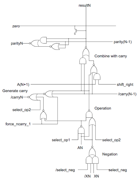
I have not experimented it yet, but a CLA might be possible, which takes the P and either a or B signals as inputs, don't you think?


Attachment:
Virtual Generate.png
Virtual Generate.png [ 33.16 KiB | Viewed 1640 times ]


To put it short: If (A=1 AND B=0) OR (A=0 AND B=1), then Cout=Cin.

The proplem is, that due to the different propagation delays, having Cin in the equation for generating G
might give you spikes in the upper chunks of the carry lookahead mechanism.
I think that's not dangerous, but it might affect overall speed because it takes some time until the signals have settled.

Another idea would be adding another FET switch for generating G.
Unfortunately, this increases capacitances...

Attachment:
slice2.png
slice2.png [ 4.57 KiB | Viewed 1640 times ]


Squonk wrote:
[Cray] I Agree, do you have some links to share?

I like the mechanical construction of the Cray-2 logic modules.
The idea of connecting the PCBs by using pogo pins is nice.
It _almost_ keeps things service friendly... but mechanical stability of such a PCB stack might become an issue.

Squonk wrote:
Yes, all these bells and whistles add to the complexity of the design, but using a bitslice does not add to it, as these must be addressed on top of the basic "ALU" macrocell itself.

Well, using an 8 Bit ALU for data calculations and a 16 Bit adder for address calculations might be another option... I think.

But when aiming for speed, trace lengths and capacitances are going to matter a lot.
So adding circuitry for making a CPU faster without carefully thinking about what you are doing and why
could backfire and actually result in the design losing some speed.


Top
 Profile  
Reply with quote  
PostPosted: Sat Apr 22, 2023 8:18 am 
Offline

Joined: Tue Apr 11, 2017 5:28 am
Posts: 68
Removed by author


Last edited by Squonk on Tue Oct 03, 2023 7:25 pm, edited 1 time in total.

Top
 Profile  
Reply with quote  
PostPosted: Sun Apr 23, 2023 10:58 am 
Offline

Joined: Tue Apr 11, 2017 5:28 am
Posts: 68
Removed by author


Last edited by Squonk on Tue Oct 03, 2023 7:26 pm, edited 2 times in total.

Top
 Profile  
Reply with quote  
Display posts from previous:  Sort by  
Post new topic Reply to topic  [ 20 posts ]  Go to page 1, 2  Next

All times are UTC


Who is online

Users browsing this forum: Google [Bot] and 7 guests


You cannot post new topics in this forum
You cannot reply to topics in this forum
You cannot edit your posts in this forum
You cannot delete your posts in this forum
You cannot post attachments in this forum

Search for:
Jump to: