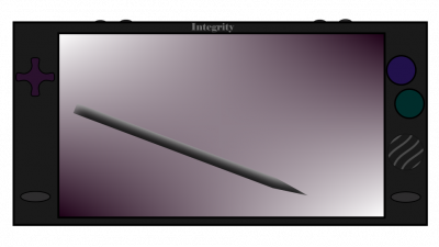
6502.org Forum  Projects  Code  Documents  Tools  Forum
It is currently Sat Apr 27, 2024 10:18 pm

All times are UTC


Post new topic Reply to topic  [ 55 posts ]  Go to page 1, 2, 3, 4  Next
Author Message
PostPosted: Sun Mar 19, 2023 7:23 pm 
Offline

Joined: Sun Mar 19, 2023 2:04 pm
Posts: 137
Location: about an hour outside of Springfield
Project "Integrity"

Standalone Core Screen Unit
Attachment:
bitmap.png
bitmap.png [ 171.5 KiB | Viewed 1960 times ]

Quote:
“A late game is only late until it ships. A bad game is bad until the end of time”
Shigeru Miyamoto

This is a long time project of mine I have been working on here and there since the 90s when I was a kid holding a cordless phone in my folk's kitchen. This is a modular portable device comprised of various units:

Financials and Open Hardware Standards
Expected Cost for the Core unit is expected to be $250-350 USD.
This includes ICs, PCB, Assembly, Screen, Battery and Shipping, as well as a margin for unexpected costs.
This number is a goal as much as an estimate, though so far we are in range. At no time shall we exceed $450 USD.
Projected Production is in 1-10s of units during development, unless externally funded.
Our goal is a run of 10,000+ Units ideally crowdfunded with pre-orders.
The specification, OS and software are largely Open Source and can be user repairable or assembled.
The Integrity from Wayfarer Technologies is a device, an Integrity, or "One's Integrity" need only conform to the specification standards.
Waytech would only directly offer customer support for the Wayfarer Technologies Integrity Mobile Computer, the community might support DIY users and 3rd party developers.

Several Peripherals are planned and offer vectors for future development or expansion. including Industrial and Scientific Computing Modules for business and education, audio modules for interfacing with recording and performance equipment, and a keyboard for development and typing. Radio communications modules and PCMCIA adapters allow for use of thousands of existing devices extending their usefulness. Hardware that conforms to the Integrity standard specification should have interoperability with any of these peripherals.

Operating System
Integrity OS <working title>
link: TBD

an 8/16-bit mixed use OS for mcu/mpu computing and development
runlevels for 8 bit 6502 work on 65816 in e-mode
runlevel 0/1 is recovery/examination/boot mode
higher runlevels for 'unlocked' hardware access or 16-bit mpu or modes (native mode)

this means the 'BIOS' ROM code, is the recovery/rescue mode code, and is the basis of the 8-bit version of the OS
when the 65816 is in 'e' mode, the OS specification calls for the lower runlevels to restrict the hardware registers to 8-bit lengths wherever possible to provide the same interfaces to the hardware, ie, 6502 software will run on the chip as expected, and 65816 software written to this runlevel spec will then run on a 6502, barring compiler options for manufacturers, type C vs type N processes etc.


Core:
Screen
~8-8.5" 800x480 WGA variable backlit LCD

Power
5+v Battery Pack or 4x 1.x Volt Cells,
Charging Unit and Jack, charger runs from USB(-C?) and any other 5v+ in sources,
USB ICs include the Max301/300 series/Max2000, 7795b, STUSB1602 etc
while 20v going near the cpu is 'scary', it should be isolated enough, there is a goal to keep power at 5v max, use an earlier or alternate standard, which offer locking industrial grade connectors, still. usb c, and usb-otg are supported and useful features
20v exceeds 12v, which allows flashing of EEPROMs and other high voltage tasks. As this is only supplied when plugged in, it may be acceptable. if so, overvoltage protection, a circuit breaker, or dedicated redundant overvoltage protection is desired if not required.
even at this point, using sockets for replacing a damaged chip becomes a choice.

5v, 3.3v are the main voltage 'rails' we are using, with a possibility of a ~1.8v rail or local voltage modification
Given that we are using PCMCIA Type-1 as a multi-port, 5v and 3.3v are required.
A few WDC chips will need 5v for 12Mhz stability, out current middle buss speed. Most ICs however will operate on the 3.3v rail or plane.
Regarding EOMA68, this well intentioned idea is hazardous due to incorrect pinouts (or documentation?). every effort will be made to detect the EOMA68 cards, reject and lockout any power on those cards, including sending shutdown signals to them until removed. These are dangerous to every computer they touch, because they failed to respect and adhere to existing standards.

CPU Logic Unit
16-Bit 65816 @12/4 Mhz (or 8/4? tbd)
this is the frontal cortex of the system, the steering and driving chip that is most directly programmed by the user or developer.
in e mode, the system will be intentionally constrained at the appropriate OSI layer, as a specification point, it is intended here that the X, Y registers be in 8-bit modes when not directly being used for 16-bit tasks, being returned to 8-bit modes afterwards. (this probably needs clarity). A low clock for the 6502 emulation mode and low speed communications may be provided by an additional clock or a clock divider circuit.

Math Co-Processor Micromega u-FPU v2 or v3, PIC33 DSP or similar

Local I/O Unit 6522 VIA chip? (or alternative micro UART chip such as MAX3100 series)
the local I/O chip is basically optional, the PIC is going to offer an order of magnitude more connectivity and utility out of the gate, it's what it was designed to do. However, in early startup, low runlevels, recovery, debugging etc; it is desirable to examine and interact with every piece of hardware, every bit. Further, having direct access to the possible 65SI Bus/65SIB connector from this UART/support I/O chip to the CPU in the CPU core section of the board with some dedicated RAM and recovery ROM does offer a 'backup and recovery system' to unbrick the device and interface with other machines. It may be possible to not include this chip or unit, and it may create a complicated layout or OS routine to support such low level redundant I/O with a PIC24 acting as a full RIOT-esque chip. However, it does offer an extra channel or two of communication, bypasses the PIC and should support the 65SIB connector, and may allow terminal type access to the CPU, the onboard ROM and allow system recovery and updates, especially if the PIC requires updates or repair.

Attachment:
Function Draft 2.png
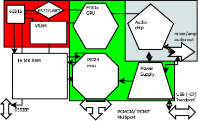
Function Draft 2.png [ 19.88 KiB | Viewed 1697 times ]


System Busses and Support Components
High Speed Video Bus 60 Mhz, GPU, Flash Memory i/o, the GPU has a 12.000 Mhz internal or external clock and a multiplier/divider
Mid Speed Common Bus 12 Mhz, PIC24 can run at up to 16 or 60depending on model, it at 60, it will bus to the GPU. The 65816 will also run at 12. Mhz in this case if the current GPU, a Bridgetek FT816 is used, to better sync up to its clocks and minimize oscillators.

RAM is being considered in full SRAM, dual port VRAM and traditional DRAM options. The system will have 16 MB of RAM, and may have additional RAM via a switch or RAM banking, allowing for 64MB of available RAM or More. the Integrity OS specification will further determine this. A major consideration is using high speed battery backed SRAM in 64K for the 6502 e mode to use as a dedicated 'fast page' or similar configurations regarding core functions of the 65c02/65816 in e mode.
RAM banking, fast ram for local pages banks, extended ram and rom chip options are being explored. The 6505/65816 have MMIO addresses for dedicated video access and control, mapping this to shared vram or FIFO buffers etc may be desireable to achieve GPU control without going through the PIC/board controller or even the 6522.

North Bridge Multimedia Controller Bridgetek EVE 24/32-Bit LCD Controller @60Mhz (or lower?)
offers LCD driver, GPU, mono sound engine, touch screen and flash rom access

South Bridge Board Controller PIC 24E series 16-bit MCU @60 MHz (or 12?)
UART, Timers, Interrupts, SPI, I2C, ALU, and USB services

Sound Generator Savage Innovations SSG01 Soundgin (or Yamaha FM-Synth or Similar, a PSG chip)
Mixer, Stereo, Amplifier, Headphone Out, On-board Speaker or speakers.

Stylus ERM stylus reporting on a resistive touch channel to North Bridge

Multiport external bus adapter (PC-Card type I or ISA Pin-compartible), USB-OtG
we are directly competing with EOMA, a well meaning but physically incompatible use of PCMCIA.
we are extending/forking the legacy PCMCIA standard, itself descended from the venerable ISA standard, into what we are calling:

PC-Card Multi-Port, or PCMP and it is pretty much PCMCIA as of revision 2.1 or later, possibly to include the entire 32-bit CardBus with DMA, though type i 8/16-bit cards are enough for now.

Controls volume, mute, reset/hardware interrupt;
. D-Pad, Face Buttons, Triggers, analog stick may be on external "Grip" unit.
. the 8-bit D-Pad, Confirm, Cancel/Back, Option/Select and Start/Menu buttons are standard on all Integrity Cores
. power, volume+/-, reset button calls hardware ROM recovery mode code direct to CPU for debugging.

Keyboard
Keyboard Unit with additional peripheral interfaces, rs-232, etc

MIDI Production Unit
a 24-Key weighted keyboard,
wavetable, midi connectors, amplifier hookups
drum pads
drone generators
wave form generators
metronome, microphone and headphone jacks

Data Sampling Unit
Multimeter Leads
Thermocouple Lead
ADC/DAC
Signal and trace generators
Oscilloscope software
Scientific Graphing Calculator Keys

Backpack
clip on shell
extra battery
extra PCMCIA slots (2 or 3)
screen cover folds to make kickstand

Earthshaker
Ballast class battery
Bass reflex tubing
multi-speaker array
mass storage array (flash for media?)
carry handle and accessory case integrated to unit
this unit can play MP3 or Ogg etc.
it has a small segmented or dot LCD, guitar jacks, etc

Spine and Binder
Spine is a simple interface strip and housing that links two units together in the form of a book
Binder is a portfolio-esque case that can hold two units with a spine or keyboard and unit.

Sketchpad
E-ink display module, greyscale, 4 or 16 tone, highlight, tint or multicolor possible
compatible with Spine and Binder, possible overlay model uses thin film to rest over Core screen as a cover.
uses the same stylus, can 'flash save' drawings and notes to the Core.

Windtalker
Radio/Ir module
CB/Packet Radio,
Local Net/Wi-fi (WPA or WEP 16-bit), etc
Universal Remote


Images and Concept Art

Standalone Core Screen Unit
Attachment:
bitmap.png
bitmap.png [ 171.5 KiB | Viewed 1960 times ]


With "Grip" Unit
Attachment:
bitmap2.png
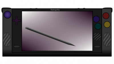
bitmap2.png [ 217.49 KiB | Viewed 1957 times ]


Last edited by wayfarer on Mon Mar 27, 2023 3:12 am, edited 20 times in total.

Top
 Profile  
Reply with quote  
PostPosted: Sun Mar 19, 2023 7:42 pm 
Offline
User avatar

Joined: Thu Dec 11, 2008 1:28 pm
Posts: 10793
Location: England
Welcome!

What stage are you at? Do you have any diagrams, or sketches, for example? Or perhaps you have some detailed ideas for circuit design?

Perhaps more important: what's your next step?


Top
 Profile  
Reply with quote  
PostPosted: Sun Mar 19, 2023 7:55 pm 
Offline

Joined: Sun Mar 19, 2023 2:04 pm
Posts: 137
Location: about an hour outside of Springfield
lots of data sheets.

not at PCB design just yet. some function block stuff. I recovered a draft of a flash deck.
at one point I had many pages full of notes, and they were lost to a move
at another point, I had been on the phone with LCD makers for the screen unit, years ago

atm, Im gearing up to prototype in the next year or so.
I am working on a BIOS demo on the emulator when I get time here and there.

my next step?
I call people next week and talk to sales reps or tech support at different places.
I need clarity on some clock speed concerns and interfacing with other chips.
finding an FM synthesizer


Top
 Profile  
Reply with quote  
PostPosted: Mon Mar 20, 2023 4:40 pm 
Offline

Joined: Sun Mar 19, 2023 2:04 pm
Posts: 137
Location: about an hour outside of Springfield
Further Info

this needs revision, I am trying to gather as much info from disparate sources here as posssible

Quote:
12 Mhz
Id like to run at 12 Mhz in native mode and either 3 or 4 Mhz in emulation mode
the other two chips are probably going to run at 60Mhz
if I end up with one chip at 16Mhz, Ill run at 8Mhz on the 65816 in native mode, and 4Mhz in emulation mode. I can set the clock on the lcd controller to 48Mhz or whatever internally with a bit.
the project is using a 65816, a PIC24 and a bridgetek lcd controller
normally the PIC model and Bridgetek IC are 60 Mhz, though the PIC24 comes in 16 (or 32??) Mhz variants
if I can get a rep on the line next week, Ill sort out if I can get the PIC at 30Mhz, in which case I might do that, it has better crypto functions an still has the full USB OtG functions
then Id set the 65816 to 10 Mhz maybe, or go 32 PIC, 8 in n and 4 in e modes
so, next week is calling people and discussing options

the PIC version we use is important, its the co-processor and board controller. its I/O pins will determine the expandability of many devices in the future. keyboards, analog sticks, docking stations input etc
March 20, 2023

so, looking over the PIC and the 65816, they both use 16MB of RAM, and similar 24-bit addressing, the Bridgetek chip use 24-bit SPI, over a dedicated 4MB control space for each of it's media functions
the bridgetek also has an internal, or is driven by a 12 Mhz oscillator, so thats probably going to drive the board
I am looking at alternatives to the Bridgetek, however, it does seem well suited to my purposes.

What I want, is a ROM BIOS that loads up in 6502 'e' mode and has as direct of control as possible over the hardware directly. so its going to set its MLB(?) pin and lock the memory to itself first. (I think) and it is going to load a very simple 'pre-boot environment' or 'micro-shell', like a runlevel 1 or something
and at this point, its a 6502 and a screen and some RAM and a few buttons.
this would be a diagnostic type mode, you would have a simple rudimentary shell with a few commands, maybe a Hex-editor or such, and it would POST here. you would basically be able to hit a button or two, and go into a 'fullmode' or select a mode here. this could be set to automatically skip this screen, or bypass this mode unless in 'recovery set' mode

so just, like, the MS-DOS on a floppy, MS-DOS.SYS, COMMAND.COM and like AUTOEXEC.BAT basically
something that fits in a tiny ROM you can unbrick the device from
uh, BIOS+, 1MB-OS type deal
so once POST is done, the device (the 65816) turns over everything to the PIC and the GPU starts doing it's thing. so prior to this, if possible, the LCD may be driven directly by the 65816 (or rather an SPI controller or if required, the GPU in a low level mode, B&W, etc) some of this is ideally customized by the user and all

so, Im not certain a 65816 can run the LCD on it's own, though if it can it should, and it should 'run' everything on the system at first and start up all of the other chips, for instance, the GPU needs a command set of what to draw, and so the 65816, the Logic chip, will load into it's 4MB space (I guess this means its using 4MB of shared memory, or better, it gets some VRAM of it's own. It has a killer PC-speaker type mono sound driver, several nice color modes, a touch screen driver I think I can get to work with a pressure sensitive stylus instead of being a touch screen. like a wacom. the PIC has a DMA controller, and some 65186 have MLB(?) pins to lock out RAM, I still wonder about maybe a dedicated bus, spi, dma controller for the 65816 instead of using the PIC's
anyway, once the system is loaded, the PIC 'runs everything', it does USB, it does SPI, it does DMA, it does ADC, it does some basic Multiplication and Division.
while the PIC has 16 registers, it works very differently to the 65816, it seems more like, idk Ladder Logic maybe, than a general purpose chip?
I do not know, Id have to read more on both, however, they seem to compliment each other well and share many characteristics.

I want to have system software that runs on the PIC, and program logic that runs on the 65816, and uses the Bridgetek LCD controller as a GPU, which I think it can do.
this is going to be in the ~$250 price range I think
because of the screen. Maybe $300. If I can get the device and a peripheral or two to $400, like a docking station and a case, or extra battery and some I/O ports, that might be ok
the chips and RAM are not much, nor will the assembly and case if done in volume, so far, I can get everything from US, Japan, Taiwan India and Korea, even the LCD, Tianma


Top
 Profile  
Reply with quote  
PostPosted: Mon Mar 20, 2023 9:01 pm 
Offline
User avatar

Joined: Wed Feb 14, 2018 2:33 pm
Posts: 1399
Location: Scotland
Well, I'm curious...

It sounds very interesting, but also somewhat odd at the same time ...

The sort of project that requires you to "talk to people" for components are the ones that are expected to ship in the 1000s or more. Often much more in these enlightened days where we go to Mouser, Digikey, etc. for even 100s or components...

So what is it?

Sounds like some sort of hand-held multi-media/PDA/data acquisition/tricorder "clamshell" type thing (in which case there are far better CPUs for it) or some sort of retro equivalent?

Using "smart" graphics controller chips - well I'm guilty of that to a degree - the other side is that even a 16Mhz '816 will struggle to manage a memory mapped 800x480 pixel display at any reasonable speed although 8bits per pixel may be feasible, even then it's 375KB or just under 6 banks of 64KB which makes even something as simple as clearing the screen an issue. if you can get a high speed SPI interface to the '816 then it could do it though - providing the commands are of the form "plot a point", "draw a line", "put up a menu with these icons, these input areas, and load these images from the on-board SD card"... (I've used 4D system smart displays in the past like that).

Not sure about your speeds - why run it slower in emulation mode? My system runs at 16Mhz in native or emulation mode. Native mode is technically harder to run faster as you have to sample and latch the upper 8 bits of the address bus at the right time...

Then the biggest crux of them all - software.

Your talk of booting - a BIOS - needing 1MB of 6502 code... Are you aware the 6502 can only normally address 64KB? Systems "of the time" typically had 2KB of "monitor" then maybe 8-12KB of BASIC then maybe up to 32KB of RAM... The BBC Micro was 12KB of Operating system and 16KB of BASIC with 32KB of RAM. This sounds like a system more complex than either the Communicator or the //gs was at the time - and that's before going into native '816 mode...

In native mode I suspect you'll eventually need an operating system to handle that. I know of 3; First is the Acorn Communicator - a sort of 65816 version of the BBC Micro. They are rare, but the ROMs are online. 2nd is the the Apple //gs where there are Pascal and C compilers for, the other is my own Ruby BCPL OS. Great if you like coding in BCPL, I guess, but while it's faster than BASIC, it's still slow.

My own thing has an ATmega as the board host controller - that runs at 16MHz with the '816. For me, it took a lot of the "heavy lifting" of IO, serial, SD card (and originally video) off the '816. And I could write all that code in C rather than 6502/816 assembler.

Anyway, please do keep us informed about progress - I don't think we've had anything really tangible in the '816 world for some time.

Cheers,

-G

_________________
--
Gordon Henderson.
See my Ruby 6502 and 65816 SBC projects here: https://projects.drogon.net/ruby/


Top
 Profile  
Reply with quote  
PostPosted: Tue Mar 21, 2023 5:18 pm 
Offline

Joined: Sun Mar 19, 2023 2:04 pm
Posts: 137
Location: about an hour outside of Springfield
drogon wrote:
Well, I'm curious...
It sounds very interesting, but also somewhat odd at the same time ...
<snip>
So what is it?

it is a modular portable device.
Quote:
Sounds like some sort of hand-held multi-media/PDA/data acquisition/tricorder "clamshell" type thing (in which case there are far better CPUs for it) or some sort of retro equivalent?

yes.

Quote:
Using "smart" graphics controller chips - well I'm guilty of that to a degree - the other side is that even a 16Mhz '816 will struggle to manage a memory mapped 800x480 pixel display at any reasonable speed although 8bits per pixel may be feasible, even then it's 375KB or just under 6 banks of 64KB which makes even something as simple as clearing the screen an issue. if you can get a high speed SPI interface to the '816 then it could do it though - providing the commands are of the form "plot a point", "draw a line", "put up a menu with these icons, these input areas, and load these images from the on-board SD card"... (I've used 4D system smart displays in the past like that).


yes, it is very difficult to run a large modern LCD screen with a 65816/6502. I am planning to use a 16-32 bit lcd driver. The one I selected has a variety of color modes, including B&W (1-), 2-,4-, 8-bit grey, and RGB332 or ARGB222 8 bit modes as well as several 16 bit graphics modes. The 65'e'02, or 65816 in e mode would only directly drive the screen or GPU during "recovery/maintenance/shell" mode. Otherwise, the GPU/Media controller is run by SPI and runs the screen using its commands written in C or manipulated by the CPU. The PIC may load command lists to the GPU via SPI etc, or I am currently exploring using the 65816 directly via shared RAM or its internal mapping. Some shared dual port RAM, a good SPI/DMA controller and/or Memory Bank Mapper/Switcher would be nice to have dedicated to the 65816, however the WDC offerings for VIA, PIA and ACIA are not [i]quite what I am looking for.
The 65816 or 6502 mode will only be 'directly' running the screen briefly and in a low color mode.
[/i]


Quote:
Not sure about your speeds - why run it slower in emulation mode? My system runs at 16Mhz in native or emulation mode. Native mode is technically harder to run faster as you have to sample and latch the upper 8 bits of the address bus at the right time...

to be more like the 6502? I had honestly thought it would run at a lower speed for some reason. I would say, if I do not need to clock it down, it saves a crystal or clock divider on the board. for some reason, back of my head, I want to say "to talk to lower speed devices on the 8-bit side, though that may be an artifact of conflagration.

Quote:
Then the biggest crux of them all - software.
Your talk of booting - a BIOS - needing 1MB of 6502 code... Are you aware the 6502 can only normally address 64KB? Systems "of the time" typically had 2KB of "monitor" ...
<snip> - and that's before going into native '816 mode...


it has been many years since I copied peeks and pokes out of a book into my C=64 in the dining room and made a yo-yo on my screen; or built a nice routine I could load from tape or 5.25" that made my screen readable. Cosmigo beige box full of games :wink:

by "1 MB" I mean "the version of MS-DOS you could fit on a 1.44MB disk. Probably not a full 1MB. It will fit on a tiny EEPROM or flash chip on the board. It will be a B&W or 4 Tone Grey screen that drives the screen as directly as possibly, probably using the onboard MMIO (Memory-Mapped Input/Output) functions if possible. There is an 8x8 and 8x16 font on the GPU, it has a good list of color modes to use. So one of the lower two should work. 800*480= 384K, so yes, a lot of RAM, however, Directly driving the LCD is unlikely, so we are pushing to the GPU anyway and I think it is not much ASM or even "timing tricks" to put lower resolution on the screen by writing each pixel and scan line multiple times, so we can get 200x120 in 32K or RAM, or 400x240 at 128K, and with a few tricks, this gets easier, like only drawing one row of tiles at the top of the screen for a menu and leaving the rest blank, or only shifting a buffer 'up' as a new prompt or text response appears and only clearing the screen on CLS commands, that sort of thing. the point here is :

a recovery mode/debugger that allows for system inspection, settings, hot saves, power management etc.
really, an overgrown text/hex editor and some icons. This device only has an onscreen KB you use with a D-Pad and Button. or a stylus by default. So, the basic "OS" is run with a D-Pad and buttons. It really should be only a few KB I guess, and the exact size is not too important, just a place you can load to and interact with your system before you launch into native mode, or use a 6502 type 'image' or ROM file/program etc. this might be a different more full fledged shell, out goal here is just basically 'boot to this floppy that has a launcher and some tools', then it should boot into "the real software OS".


Quote:
In native mode I suspect you'll eventually need an operating system to handle that. I know of 3; First is the ...

yes, a basic shell in 6502 8 bit mode, (which is more full fledged than "Recovery" mode though more like "a higher [i]runlevel than recovery mode, more stuff will be on, the CPU wont be locking out everything else and trying to slowly do everything by itself); this is pretty 8-bit, Id actually look at something like the Famicom DOS or such, something with a game controller.
[/i]


Quote:
My own thing has an ATmega as the board host controller - that runs at 16MHz with the '816. For me, it took a lot of the "heavy lifting" of IO, serial, SD card (and originally video) off the '816. And I could write all that code in C rather than 6502/816 assembler.

Anyway, please do keep us informed about progress - I don't think we've had anything really tangible in the '816 world for some time.

Cheers,

-G


Yeah for sure, Im looking at 12Mhz because the LCD native controller in 12 MHz+multiplier, and its a nice spot, I might alter it some. There is a CS4218 sound chip that wants a 12.288 Mhz crystal and I want to know if that will work, save space and parts.
Clock speed may change, atm 12Mhz sounds good and is a 5x multiplier to the 60Mhz chips of the other two for PLLs and such.
I am planning at the moment to use a PIC24 because they have similar addressing and it is a nice microcontroller to work with the microprocessor. lots of I/O and maintenance functions.

So what is the Integrity, a semi-open game tablet and hardware spec that has a variety of modules that alter its function and form.

the 6502 mode stuff will be 'there', and most of the focus will be on 65816 16-bit mode, though due to the 65816 starting and (iirc resetting to) in 6502 mode, having a good ASM, well Basic Input Output System with a 'Preboot' environment or some kind of hardware encoded 'runlevel' that can be accessed is probably a good thing. If I can, there will be a button you press that will drop you to this screen by initiating a hardware IRQ that loads this runlevel at any time, and maybe snapshots your last game or program image (like an emulator save state) and you can shutdown, sleep, inspect, hex edit, configure, switch modes etc from. returning to the 16-bit shell should be a few taps or presses away. so, this is maybe going to have, like 4-6 "menus"
"Return to Normal Operation/Launch Awesome 16-bit OS"
Settings and Configuration
System Examiner/Hex Viewer-Editor
go to 6502 shell runlevel up
Power Stuff
??? - next page of menus?


There are a lot of questions to answer here and I am going to go through them one by one, and update the first post with new information, links to google docs etc.


Top
 Profile  
Reply with quote  
PostPosted: Tue Mar 21, 2023 5:35 pm 
Offline
User avatar

Joined: Fri Dec 11, 2009 3:50 pm
Posts: 3346
Location: Ontario, Canada
BigEd wrote:
What stage are you at? Do you have any diagrams, or sketches, for example?
wayfarer wrote:
lots of data sheets.

not at PCB design just yet. some function block stuff.

Welcome, wayfarer. :) It would be good if you can share the function block stuff. Most especially, it would be good to see an overall block diagram of the entire system. Ideally that'd show the various buses between blocks.

-- Jeff

_________________
In 1988 my 65C02 got six new registers and 44 new full-speed instructions!
https://laughtonelectronics.com/Arcana/ ... mmary.html


Top
 Profile  
Reply with quote  
PostPosted: Tue Mar 21, 2023 6:02 pm 
Offline
User avatar

Joined: Fri Aug 30, 2002 1:09 am
Posts: 8428
Location: Southern California
Commenting on this:
wayfarer wrote:
Quote:
Not sure about your speeds - why run it slower in emulation mode? My system runs at 16Mhz in native or emulation mode. Native mode is technically harder to run faster as you have to sample and latch the upper 8 bits of the address bus at the right time...

to be more like the 6502? I had honestly thought it would run at a lower speed for some reason. I would say, if I do not need to clock it down, it saves a crystal or clock divider on the board. for some reason, back of my head, I want to say "to talk to lower speed devices on the 8-bit side, though that may be an artifact of conflagration.
and this:
Quote:
the 6502 mode stuff will be 'there', and most of the focus will be on 65816 16-bit mode [...] returning to the 16-bit shell should be a few taps or presses away [...] go to 6502 shell runlevel up [...]
Note that the 65816's native mode allows you to select register sizes, whether the accumulator is 8- or 16-bit, and separately, whether the index registers are 8- or 16-bit.  It's best to think of the m and x bits not as mode bits, but rather as register-size bits that take effect in native mode.  Really the only mode bits are d (which the 6502 also has) and e.  The processor comes out of reset in 65c02-emulation mode; but then if you don't need to run any '02 software, you can put it in '816 native mode and leave it there, never touching that e bit again.  It sounds to me like you could do this, and it would make things easier.  Note that when you first go into native mode, the register sizes are still 8-bit, and you can switch back and forth, between 8- and 16-bit (again with the accumulator size and index register size not locked to each other), on the fly, as often as you want, without leaving native mode.  See the article on common '816 misunderstandings at http://wilsonminesco.com/816myths/ .

_________________
http://WilsonMinesCo.com/ lots of 6502 resources
The "second front page" is http://wilsonminesco.com/links.html .
What's an additional VIA among friends, anyhow?


Top
 Profile  
Reply with quote  
PostPosted: Tue Mar 21, 2023 10:38 pm 
Offline

Joined: Sun Mar 19, 2023 2:04 pm
Posts: 137
Location: about an hour outside of Springfield
GARTHWILSON wrote:
Note that the 65816's native mode allows you to select register sizes, whether the accumulator is 8- or 16-bit, and separately, whether the index registers are 8- or 16-bit.  It's best to think of the m and x bits not as mode bits, but rather as register-size bits that take effect in native mode. Really the only mode bits are d (which the 6502 also has) and e.

[color=#0000BF]ah, okay, I get how you are thinking sure. these bits put those registers in 8- or 16-bit modes.
Can you set them independently so X is 8 and Y is 16 bits or vice-versa?
say to store several 24-bit addresses in a list briefly or something

Quote:
The processor comes out of reset in 65c02-emulation mode; but then if you don't need to run any '02 software, you can put it in '816 native mode and leave it there, never touching that e bit again.  It sounds to me like you could do this, and it would make things easier.  Note that when you first go into native mode, the register sizes are still 8-bit, and you can switch back and forth, between 8- and 16-bit (again with the accumulator size and index register size not locked to each other), on the fly, as often as you want, without leaving native mode.  See the article on common '816 misunderstandings at http://wilsonminesco.com/816myths/ .[/color]


Yeah, this is precisely why there is going to be a recovery mode or runlayer. this 8-bit BIOS/Debug mini-OS I am talking about. the BIOS, or pre-loader. I posted some pictures. Im not certain the two units are separate. Either way, the unit 'starts' in 6502 mode and because of this default behavior, and to support any user desire to utilize a 6502, indeed, going into a lower speed and lower power for 8-bit games and apps, should allow the device to work longer on a charge. in the pictures there are 4 'nubs' along the top of the Core, the right side is probably a hardware volume control. there may be a mute button or a pot-wheel. the other sude is the Power button, and the 'Recovery' button, instead of say, 'reset'. It is going to trigger a Hardware IRQ and try to load the system to that Recovery BIOS+System, the BIOSIS. This is not, the 'main menu' of the device, this is comparable to hitting a Function Key in say, Linux, and it dropping from GNOME to Bash, going from runlevel 5 to 3 or whatever. The machine will drop into its 8-bit boot up 65e02 mode, lock out RAM and other devices and give the user and the CPU, basically full control. if I could bypass the GPU here I would.

Now, other than this, the device will be able to then launch software in 8-bit mode, or run in full 16-bit mode with all circuits running.
At this point, speaking of a function diagram, I am pretty sure Im going to use SPI, even if by doing so manually. I would like, an SPI/DMA controller combination that would let me switch between 4 Banks of RAM... like a memory mapper kinda

I did see the stuff about SPI65? is this the local bus standard? I will look into that.
Personally, I was going to try to build around PCMCIA standards for 16-bi cards.
I will end up with some 32 bit chips on here, the GPU, the Math Co-processor, etc.

Now, once this system is running in 'full-mode', is a PIC24 (@60 Mhz, the E512GU/GP one, or a PIC24F etc, dsp33) a good companion choice for the board controller?

I am rather trying to avoid the big DIP 65xx companion chips, they are not so great on real estate, though I am wondering if I can operate without one...
dual port RAM, other tricks maybe.

SPI seems pretty crucial, PCMCIA is probably going to be my 'multiport'.

It is good to meet you Mr Wilson, I have been browsing your site! You certainly know the 6502/65816 incredibly well.
I look forward to working with you, you seem to have a solid grasp of some of this hardware.
It seems like the ACIA chip is almost a 'must have' and you certainly demonstrate you can do a lot with it; however, on a mobile device space is limited, is there a good alternative or is the PIC24 or an msp430 etc a good choice?


Top
 Profile  
Reply with quote  
PostPosted: Tue Mar 21, 2023 11:56 pm 
Offline
User avatar

Joined: Fri Aug 30, 2002 1:09 am
Posts: 8428
Location: Southern California
wayfarer wrote:
Can you set them independently so X is 8 and Y is 16 bits or vice-versa?

No, the two index registers must be the same size, although that size is independent of the size of the accumulator.

Ah, so you do want to be able to run legacy 6502 software.  This was a requirement for the Apple IIGS design.


Quote:
any user desire to utilize a 6502, indeed, going into a lower speed and lower power for 8-bit games and apps, should allow the device to work longer on a charge.

Lowering the clock rate will lower the power usage, but I don't think '02-emulation mode will really save significant power over native mode.  The 816's specified current for the processor itself is 2mA max per MHz, regardless of whether it's in native mode or not, with their tester load.

Quote:
I did see the stuff about SPI65? is this the local bus standard? I will look into that.

If you mean 65SIB, a few of us have made equipment with it.  It's an external serial interface bus, hobbyist-friendly, compatible with SPI, Microwire, and dumb shift registers, but more flexible.  The "65" part of the name is for the 6502.org forum, not that it's particular to the 65xx processors.  It could be implemented just as easily with other processors too.

OTOH, if you mean Daryl's 65SPI chip (I know the names are confusing), I know several have used that too.  The original CPLD he used to make them became unavailable (probably discontinued because it was so power-hungry and ran hot), so he re-designed it to use the Atmel ATF1504 CPLD.  He no longer programs and sells them, but he does provide the code for you to program your own, at the linked page.


Quote:
I am rather trying to avoid the big DIP 65xx companion chips, [as] they are not so great on real estate

They are available in PQFP, if you want to solder that tiny stuff.  So far, I have stopped at PLCC.

Quote:
It seems like the ACIA chip is almost a 'must have' and you certainly demonstrate you can do a lot with it; however, on a mobile device space is limited, is there a good alternative or is the PIC24 or an msp430 etc a good choice?

The '51 ACIA, particularly with the bug in WDC's current offerings, has somewhat fallen out of favor.  There are workarounds for its deficiencies; but for new designs, people are choosing other UARTs, including the 28L92.  Unfortunately that one has recently been discontinued.  See this forum topic, which also gives alternatives that are partially compatible.  I have not used the PIC24 so far, only the PIC16 which I suspect uses the same SSP module(s), and it was much harder to get it going than the '51 was.  I can provide my code if it might help.

_________________
http://WilsonMinesCo.com/ lots of 6502 resources
The "second front page" is http://wilsonminesco.com/links.html .
What's an additional VIA among friends, anyhow?


Top
 Profile  
Reply with quote  
PostPosted: Wed Mar 22, 2023 5:53 pm 
Offline
User avatar

Joined: Thu May 28, 2009 9:46 pm
Posts: 8147
Location: Midwestern USA
wayfarer wrote:
ah, okay, I get how you are thinking sure. these bits put those registers in 8- or 16-bit modes.

There are no “8- or 16-bit modes”. There is emulation mode and native mode. Registers may be set to 8- or 16-bit sizes by manipulating the m and x bits in the status register. The 65C816’s operation doesn’t change due to changing register sizes. Hence it is incorrect to use the terms “8-bit mode” or “16-bit mode.”

_________________
x86?  We ain't got no x86.  We don't NEED no stinking x86!


Top
 Profile  
Reply with quote  
PostPosted: Fri Mar 24, 2023 5:28 am 
Offline

Joined: Fri Mar 24, 2023 4:54 am
Posts: 3
Sound Generator Savage Innovations Soundgin?

Where are you going to get those?


Top
 Profile  
Reply with quote  
PostPosted: Fri Mar 24, 2023 4:04 pm 
Offline

Joined: Fri Mar 24, 2023 4:54 am
Posts: 3
If you are needing these in bulk, I can get them for you.


Top
 Profile  
Reply with quote  
PostPosted: Fri Mar 24, 2023 10:06 pm 
Offline

Joined: Sun Mar 19, 2023 2:04 pm
Posts: 137
Location: about an hour outside of Springfield
smsavage32 wrote:
If you are needing these in bulk, I can get them for you.


excellent news, locating a supply of any kind of FM-synth or sound chip has not yielded much out there except a few NOS Yamaha and related chips, from shady suppliers. 6 voices is 3x each for full stereo sound going to the mixer, and a lot of nice options for various effects. I do not see a better SPU for this project available, I think it is a perfect fit.

For the specification I am going to say you need to include a sound generation system capable of creating at least stereo sound with the 3 common wave forms and ADSR envelope capability, and a stereo mixer.

I have a call scheduled with a supplier on monday, I am going to aim for at least 1000 units through crowdfunding or pre-orders. I can cold call community colleges and trade schools that teach Ladder Logic and sell 1000 units. Really, the goal, is to try to crowd source and get pre-orders on 10,000 units. That, would be a real dream come true.

Speaking of the specification: Industrial or commercial grade hardware components will be used and adherence to specifications such as IP67 or similar will be followed wherever pragmatic to do so.

Good to meet you Mr Savage. I expect you will find a few people here who might enjoy using your chips.


Top
 Profile  
Reply with quote  
PostPosted: Mon Mar 27, 2023 3:18 am 
Offline

Joined: Sun Mar 19, 2023 2:04 pm
Posts: 137
Location: about an hour outside of Springfield
Dr Jefyll wrote:
BigEd wrote:
What stage are you at? Do you have any diagrams, or sketches, for example?
wayfarer wrote:
lots of data sheets.

not at PCB design just yet. some function block stuff.

Welcome, wayfarer. :) It would be good if you can share the function block stuff. Most especially, it would be good to see an overall block diagram of the entire system. Ideally that'd show the various buses between blocks.

-- Jeff

Attachment:
Function Draft 1.png
Function Draft 1.png [ 9.98 KiB | Viewed 1697 times ]

just the start of one, Im starting high level and I am going to dive into each section further.
Right now, I want to get that Red section in the first post. figured out, thats the main logic unit of the system, and should be able to mostly operate on its own, with the rest of the hardware halted or powered down, that also leaves the PSU power unit, and I am not certain the 65SIB is going to get its 12v, though it might be possible to use when plugged in on the "high voltage service buss", atm, a 12v buss to flash eeproms with maybe. Ill have a better block diagram in a few days.


Top
 Profile  
Reply with quote  
Display posts from previous:  Sort by  
Post new topic Reply to topic  [ 55 posts ]  Go to page 1, 2, 3, 4  Next

All times are UTC


Who is online

Users browsing this forum: No registered users and 31 guests


You cannot post new topics in this forum
You cannot reply to topics in this forum
You cannot edit your posts in this forum
You cannot delete your posts in this forum
You cannot post attachments in this forum

Search for:
Jump to: