6502.org Forum  Projects  Code  Documents  Tools  Forum
It is currently Sun Apr 28, 2024 5:18 pm

All times are UTC


Post new topic Reply to topic  [ 25 posts ]  Go to page Previous  1, 2
Author Message
 Post subject: Re: 6520 dissection
PostPosted: Wed Dec 07, 2022 10:18 am 
Offline
User avatar

Joined: Fri Nov 09, 2012 5:54 pm
Posts: 1392
8) PB0 //PORT B

8 Bit I\O port, with push/pull outputs and _no_ pullup FET to VCC.

Layout for PB0..PB7 is similar, with some variations to make better use of chip space,
so we just focus on PB0.

;---

First for the output side:

DDRB0 (data direction register B) configurates,
whether PB0 works as an input (DDRB0=0)
or as an output (DDRB0=1).

It is cleared by RST during a hardware reset, defaulting PORT B to input.

DDRB0 is built around a gated RS flipflop.
High_active register write control signal W_DDRB clears/sets DDRBA0
according to the 6520 internal write data bus lines D0in and D0in#.

The high_active output of DDRB0 goes together with high_active register read control signal
R_DDRB into an "open collector" NAND gate, with the output connected to low_active
6520 internal read data bus line D0out#.

;...

The PRB0 (PORT B) data output register is built around another RS flipflop.

High_active register write control signal W_PRB clears/sets the PRB0 register
according to the 6520 internal write data bus lines D0in and D0in#.

The RS flipflop is cleared by RST during a hardware reset.

We have two NOR gates with push/pull output, controlling the FETs of the
PB0 output driver which are switching the PB0 pad either to GND or to VCC.

The high_active output of the DDRB0 register goes through an inverter, then into both NOR gates.

The low_active output of the PRB0 register goes into the NOR gate which drives
the FET switching PB0 to VCC.

The low_active output of the PRB0 register goes through an inverter,
then into the other NOR gate which drives the FET switching PB0 to GND.

;---

At the input side, the signal from the PRB0 pad goes through an inverter,
then into a 2:1 multiplexer built from a combination gate which
implements two AND gates feeding a NOR gate.

Means the output of the multiplexer is inverted.
It goes together with the high_active register read control signal R_PRB
into an "open collector" NAND gate, with the output connected to low_active
6520 internal read data bus line D0out#.

The other input of the 2:1 multiplexer is fed by the inverted output of the PRB0 register.
The multiplexer is controlled by DDRB0.

Means if PB0 works as an input, reading PRB gives the CPU what's on the PB0 pad.
If PB0 works as an output, reading PRB gives the CPU what's in the PRB0 register.

So when PB0 drives a large (capacitive) load when working as an output,
and it takes some time until the voltage at PB0 has reached the desired logic level,
the CPU still would be reading the correct/desired value from the PRB0 register.
And you won't have to worry when using read/modify/write instructions aiming for PRB.

But be aware:
If you have a glitch on PB0 when reading PRB0 in "input mode",
that glitch shows up on the 6502 data bus, too.
For better signal integrity, I would suggest to sample PB0 by a transparent latch
during PHI2=0 when building your own TTL or FPGA implementation of the 6520,
before sending it into the 2:1 multiplexer.

Attachment:
si6520_8_pb0.png
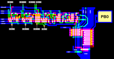
si6520_8_pb0.png [ 83.56 KiB | Viewed 376 times ]

Attachment:
6520_8_pb0.png
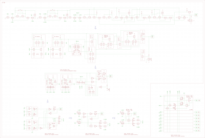
6520_8_pb0.png [ 224.4 KiB | Viewed 376 times ]


Top
 Profile  
Reply with quote  
 Post subject: Re: 6520 dissection
PostPosted: Wed Dec 07, 2022 10:20 am 
Offline
User avatar

Joined: Fri Nov 09, 2012 5:54 pm
Posts: 1392
9) CA1 input

Note, that the CA1 pad has no pullup to VCC inside the 6520 chip.
And that CA1 has a Schmitt trigger input.

Tied to the CA1 pad, we have an edge detector sampling CA1 during PHI2,
it sets CRA7 (the CA1 interrupt flag) by high_active signal SET_CRA7
when detecting an active CA1 edge.

Active CA1 edge is selected by CRA1:
CRA1=0: CA1 falling edge detect
CRA1=1: CA1 rising edge detect

To me, the circuitry looks a bit odd (the part where signal CRA7 goes into it),
and I wonder why Bill Mensch (TM) had implemented it that way.
My guess is, that it compensates for something that might happen when/while/after CRA7 is cleared.

Maybe somebody (not me) should write a technical article about this.

Point is, that we have that sort of edge detector at the CA1, CA2, CB1, CB2 pad.
Chip layout does vary for making better use of chip space,
but from the logic design point of view these 4 edge detectors are more or less identical.

And it's pretty similar to what we had in the 6522 dissection.
//For more details on the edge detector circuitry, please go there.

Attachment:
si6520_9_ca1.png
si6520_9_ca1.png [ 36.13 KiB | Viewed 376 times ]

Attachment:
6520_9_ca1.png
6520_9_ca1.png [ 144.09 KiB | Viewed 376 times ]


Top
 Profile  
Reply with quote  
 Post subject: Re: 6520 dissection
PostPosted: Wed Dec 07, 2022 10:22 am 
Offline
User avatar

Joined: Fri Nov 09, 2012 5:54 pm
Posts: 1392
10a) CA2 input

At the input side, we have an edge detector similar to "9) CA1" sampling CA2 during PHI2.

When sensing an active edge, it sets CRA6 (CA2 interrupt flag) by high_active signal SET_CRA6.

Note, that CA2 has a Schmitt trigger input plus a pullup FET to VCC.
//CA1, CB1, CB2 inputs have _no_ pullup FET to VCC.

Active CA2 edge is selected by CRA4:
CRA4=0: CA2 falling edge detect
CRA4=1: CA2 rising edge detect

Attachment:
si6520_10a_ca2_in.png
si6520_10a_ca2_in.png [ 42.5 KiB | Viewed 376 times ]

Attachment:
6520_10a_ca2_in.png
6520_10a_ca2_in.png [ 145.54 KiB | Viewed 376 times ]


Top
 Profile  
Reply with quote  
 Post subject: Re: 6520 dissection
PostPosted: Wed Dec 07, 2022 10:24 am 
Offline
User avatar

Joined: Fri Nov 09, 2012 5:54 pm
Posts: 1392
10b) CA2 output

Basically, the low_active /Q output of a RS flipflop goes into an "open collector" inverter,
which switches the CA2 pad to GND if /Q is high.
A pullup FET ties the CA2 pad to VCC.

If CA2 is configurated as an input by CRA5=0,
this forces /Q to low by overriding anything else that goes into the RS flipflop,
so that the "open collector" inverter is unable to switch CA2 to GND.

Control signals CRA3 and CRA4 then select, what sets or clears the RS flipflop
(and what comes out at CA2 if CA2 is configurated to work as an output).

We had something similar in the 6522 dissection.

Attachment:
si6520_10b_ca2_out.png
si6520_10b_ca2_out.png [ 59.06 KiB | Viewed 376 times ]

Attachment:
6520_10b_ca2_out.png
6520_10b_ca2_out.png [ 169.27 KiB | Viewed 376 times ]


Top
 Profile  
Reply with quote  
 Post subject: Re: 6520 dissection
PostPosted: Wed Dec 07, 2022 10:26 am 
Offline
User avatar

Joined: Fri Nov 09, 2012 5:54 pm
Posts: 1392
11) CB1 input

We have an edge detector similar to "9) CA1" sampling CB1 during PHI2.

When sensing an active edge, it sets CRB7 (CB1 interrupt flag) by high_active signal SET_CRB7.

Note, that CB1 has a Schmitt trigger input without a pullup FET to VCC.

Active CB1 edge is selected by CRB1:
CRB1=0: CB1 falling edge detect
CRB1=1: CB1 rising edge detect

Attachment:
si6520_11_cb1.png
si6520_11_cb1.png [ 35.15 KiB | Viewed 376 times ]

Attachment:
6520_11_cb1.png
6520_11_cb1.png [ 148.43 KiB | Viewed 376 times ]


Top
 Profile  
Reply with quote  
 Post subject: Re: 6520 dissection
PostPosted: Wed Dec 07, 2022 10:28 am 
Offline
User avatar

Joined: Fri Nov 09, 2012 5:54 pm
Posts: 1392
12a) CB2 input

At the input side, we have an edge detector similar to "9) CA1" sampling CB2 during PHI2.

When sensing an active edge, it sets CRB6 (CB2 interrupt flag) by high_active signal SET_CRB6.

Note, that CB2 has a Schmitt trigger input without a pullup FET to VCC.

Active CB2 edge is selected by CRB4:
CRB4=0: CB2 falling edge detect
CRB4=1: CB2 rising edge detect

Attachment:
si6520_12a_cb2_in.png
si6520_12a_cb2_in.png [ 34.41 KiB | Viewed 376 times ]

Attachment:
6520_12a_cb2_in.png
6520_12a_cb2_in.png [ 141.15 KiB | Viewed 376 times ]


Top
 Profile  
Reply with quote  
 Post subject: Re: 6520 dissection
PostPosted: Wed Dec 07, 2022 10:29 am 
Offline
User avatar

Joined: Fri Nov 09, 2012 5:54 pm
Posts: 1392
12b) CB2 output

It is similar to what we had in "10b) CA2 output".

Except that CB2 has a push/pull output without a pullup FET to VCC.

Basically, the low_active /Q output of a RS flipflop goes through an inverter,
then into the driver which switches the CB2 pad either to GND or to VCC.

The driver is enabled by low_active signal CB2_OE#,
which is just the inverted CRB5 register Bit.

If CA2 is configurated to work as an input by CRB5=0,
this forces /Q to low by overriding anything else that goes into the RS flipflop.

Control signals CRB3 and CRB4 then select, what sets or clears the RS flipflop
(and what comes out at CB2 if CB2 is configurated to work as an output).

Attachment:
si6520_12b_cb2_out.png
si6520_12b_cb2_out.png [ 78.19 KiB | Viewed 376 times ]

Attachment:
6520_12b_cb2_out.png
6520_12b_cb2_out.png [ 245.99 KiB | Viewed 376 times ]


Top
 Profile  
Reply with quote  
 Post subject: Re: 6520 dissection
PostPosted: Wed Dec 07, 2022 10:44 am 
Offline
User avatar

Joined: Fri Nov 09, 2012 5:54 pm
Posts: 1392
That's all for now.

8551 is supposed to be next.
//HMOS-II implementation of the 6551 UART.


Top
 Profile  
Reply with quote  
 Post subject: Re: 6520 dissection
PostPosted: Wed Dec 07, 2022 10:46 am 
Offline
User avatar

Joined: Fri Nov 09, 2012 5:54 pm
Posts: 1392
Them chip dissections are quite labour intensive.
We wanted to have everything NMOS parallel I\O covered by the end of 2022, and we did.
2022 was a crazy year for sure.
Quality of the 8521 and 6520 dissection has dropped a little bit, but it's still good enough.

///You know that the work you are doing isn't too healthy when you start playing Godzilla themes in a loop.

Our plan was to go for the MOS video chips in 2023: VIC-I, VIC-II, TED, maybe VDC.
However, I can't estimate how much spare time I'm going to have at hands in 2023,
because there are some real life problems ahead in 2023, which will sure affect my productivity.

Hmm... spending some time in court if things go South is the downside of renting an apartment to somebody...


Top
 Profile  
Reply with quote  
 Post subject: Re: 6520 dissection
PostPosted: Wed Dec 07, 2022 11:37 am 
Offline
User avatar

Joined: Thu Dec 11, 2008 1:28 pm
Posts: 10793
Location: England
Fantastic! (Not the time in court thing, that sounds like a drag, but the dissections and the results thing.)


Top
 Profile  
Reply with quote  
Display posts from previous:  Sort by  
Post new topic Reply to topic  [ 25 posts ]  Go to page Previous  1, 2

All times are UTC


Who is online

Users browsing this forum: Dr Jefyll, Martin A, Paganini and 16 guests


You cannot post new topics in this forum
You cannot reply to topics in this forum
You cannot edit your posts in this forum
You cannot delete your posts in this forum
You cannot post attachments in this forum

Search for:
Jump to: