6502.org Forum  Projects  Code  Documents  Tools  Forum
It is currently Fri May 17, 2024 5:09 am

All times are UTC


Post new topic Reply to topic  [ 256 posts ]  Go to page Previous  1 ... 6, 7, 8, 9, 10, 11, 12 ... 18  Next
Author Message
PostPosted: Tue Jun 28, 2022 5:30 pm 
Offline

Joined: Fri Mar 18, 2022 6:33 pm
Posts: 443
Here is my oscilloscope:

Attachment:
20220628_114535.jpg
20220628_114535.jpg [ 3.48 MiB | Viewed 975 times ]


It's a Tektronix 2235 analog scope. I picked it up un eBay a few weeks ago; the seller accepted my (very low) offer, I think mainly because it had no probes, and therefore they couldn't test it. It has an "Appalachian State University" badge on it, so I guess it's school surplus. It's in great shape! Aside from some minor scuffing on the case the only damage is that the clear scale for channel 1 is half missing. The remaining half fell off the knob the first time I turned it. That's no big deal, though, because I can use the channel 2 scale for reference.

Anyway, after getting the scope calibrated using its built-in square wave, it seemed like the clock signals were a logical thing to investigate. The RC6502 has two clock signals on the bus. Phi0, also known as "CLOCK," comes off of the clock / reset module. This is the clock input to the CPU module; by design the CPU module is the *ONLY* module that uses this signal. All the other modules use the Phi2 signal, which is the 6502's clock output. Based on my reading, I do not think that this is a good idea, but so it goes. When I make my own SBC instead of studying someone else's design I will do it differently. :) I have learned a lot from this project, and this is one of those things. My own LCD / keyboard I/O board takes the Phi0 signal off the bus.

The RC Project Platform board I've mentioned before has all the bus signals broken out into a header. Probing the clock lines directly makes Blue April crashy. Since I was just recently reading about cross talk, ground bounce, high frequency noise, reflection, and bus termination, this did not surprise me. Blue April's bus is about 3 times as long as it was designed to be, and it's not terminated. I believe 75 ohms is the correct termination, but I don't have any 75 ohm resistors. So, in the electronics hobbyist spirit of "close enough is good enough" and "let's try it and see what happens," I put some 100 ohm resistors on the breadboard and connected the clock lines to them. This seemed to work OK.

Attachment:
20220628_115840.jpg
20220628_115840.jpg [ 3.52 MiB | Viewed 975 times ]


Here are the two clock signals stacked up for comparison, Phi 0 over Phi 2:

Attachment:
20220628_122622.jpg
20220628_122622.jpg [ 3.58 MiB | Viewed 975 times ]


I believe that's 1 volt per division, and the field of view is 1 microsecond.

And here's Phi 0 with the B sweep zoomed in on the rising edge:

Attachment:
20220628_120441.jpg
20220628_120441.jpg [ 3.51 MiB | Viewed 975 times ]


And here's Phi 2 with the same settings:

Attachment:
20220628_120700.jpg
20220628_120700.jpg [ 3.46 MiB | Viewed 975 times ]


There are probably some things I can do to get a cleaner signal; I don't (yet!) have those nifty ground springs, for example.

I was also able see the data and latch signals for my keyboard circuit - they look GREAT! I didn't take a photo though. With single-sweep mode you basically need professional photography equipment to capture the moment. I can see why people like DSO scopes!

_________________
"The key is not to let the hardware sense any fear." - Radical Brad


Top
 Profile  
Reply with quote  
PostPosted: Wed Jun 29, 2022 1:30 am 
Offline
User avatar

Joined: Thu May 28, 2009 9:46 pm
Posts: 8188
Location: Midwestern USA
Paganini wrote:
Here is my oscilloscope...

What are you using for probes?

_________________
x86?  We ain't got no x86.  We don't NEED no stinking x86!


Top
 Profile  
Reply with quote  
PostPosted: Wed Jun 29, 2022 5:10 am 
Offline

Joined: Fri Mar 18, 2022 6:33 pm
Posts: 443
BigDumbDinosaur wrote:
Paganini wrote:
Here is my oscilloscope...

What are you using for probes?


I got some inexpensive Hantek ones to get started with. I doubt they will last for decades the way the OEM ones do, but the specs were right and they got good reviews. I tracked down the recommended replacement for the missing OEM probes, and they cost over twice as much as I paid for the whole unit! They will be for a future "rainy day" upgrade. :)

_________________
"The key is not to let the hardware sense any fear." - Radical Brad


Top
 Profile  
Reply with quote  
PostPosted: Wed Jun 29, 2022 6:00 am 
Offline
User avatar

Joined: Thu May 28, 2009 9:46 pm
Posts: 8188
Location: Midwestern USA
Paganini wrote:
BigDumbDinosaur wrote:
Paganini wrote:
Here is my oscilloscope...

What are you using for probes?


I got some inexpensive Hantek ones to get started with. I doubt they will last for decades the way the OEM ones do, but the specs were right and they got good reviews. I tracked down the recommended replacement for the missing OEM probes, and they cost over twice as much as I paid for the whole unit! They will be for a future "rainy day" upgrade. :)

I'm not familiar with Hantek probes. Are they compensated? Also, are you taking your readings with the probes in the ×10 setting?

_________________
x86?  We ain't got no x86.  We don't NEED no stinking x86!


Top
 Profile  
Reply with quote  
PostPosted: Wed Jun 29, 2022 5:36 pm 
Offline

Joined: Fri Mar 18, 2022 6:33 pm
Posts: 443
BigDumbDinosaur wrote:
Paganini wrote:
BigDumbDinosaur wrote:
Paganini wrote:
Here is my oscilloscope...

What are you using for probes?


I got some inexpensive Hantek ones to get started with. I doubt they will last for decades the way the OEM ones do, but the specs were right and they got good reviews. I tracked down the recommended replacement for the missing OEM probes, and they cost over twice as much as I paid for the whole unit! They will be for a future "rainy day" upgrade. :)

I'm not familiar with Hantek probes. Are they compensated? Also, are you taking your readings with the probes in the ×10 setting?


I practiced with both settings; the pictures of my clock signals above are using 10x. At 1x the waveform looks like a sawtooth, I gather because it's missing too many high-frequency modes. Here are the specs for the probes:

    Specification:

  • System BandWidth: x1: DC-6MHz; x10: DC-100MHz
  • Attenuation: x1/x10
  • Input Resistance: 10M ohms / 1M ohms
  • Input Capacitance: x1 85pF-115pF; x10 18.5pF-22.5pF
  • Compensation Scope: 20pF-40pF
  • Input Voltage: x1: <200V DC + Peak AC; x10: <600V DC + Peak AC
  • Weight: 55g
  • Cable Length: 120 cm
  • Temperature Scope: Operation/-10 to +50celsiu, None Operatin/-20 to+75 celsiu
  • Humidity: under 85 percent

_________________
"The key is not to let the hardware sense any fear." - Radical Brad


Top
 Profile  
Reply with quote  
PostPosted: Wed Jun 29, 2022 7:58 pm 
Offline
User avatar

Joined: Thu May 28, 2009 9:46 pm
Posts: 8188
Location: Midwestern USA
The probe specs seem to be okay. While I wouldn't say they aren't affecting what you are observing, it would seem that with the specs you quoted, the effect on signal quality should be small. Can you please post a picture of what the calibration signal looks like?

_________________
x86?  We ain't got no x86.  We don't NEED no stinking x86!


Top
 Profile  
Reply with quote  
PostPosted: Wed Jun 29, 2022 9:01 pm 
Offline

Joined: Fri Mar 18, 2022 6:33 pm
Posts: 443
BigDumbDinosaur wrote:
The probe specs seem to be okay. While I wouldn't say they aren't affecting what you are observing, it would seem that with the specs you quoted, the effect on signal quality should be small. Can you please post a picture of what the calibration signal looks like?


Sure! The calibration signal is 500mV P-P at 1kHz. Here's .5 V/division by .2 ms in 10x mode:

Attachment:
20220629_165304.jpg
20220629_165304.jpg [ 3.44 MiB | Viewed 897 times ]

_________________
"The key is not to let the hardware sense any fear." - Radical Brad


Top
 Profile  
Reply with quote  
PostPosted: Sat Jul 02, 2022 8:06 pm 
Offline

Joined: Fri Mar 18, 2022 6:33 pm
Posts: 443
It's time to start working on something I've wanted for a while now, and that is: honest to goodness old school CRT video!

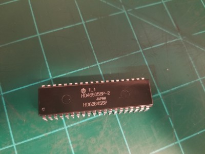
A while back I bought several of these Hitachi CRT controllers on eBay:

Attachment:
20220701_193855.jpg
20220701_193855.jpg [ 3.71 MiB | Viewed 851 times ]


They are used pulls from working systems. The legs are a little grody, so I'll use a machine-pin IC socket even during breadboarding to avoid putting too much stress on them. These are pretty close copies of the Motorola MC6845 CRTC, with a few enhanced features. One of those enhanced features is that it can take up to a 3.7Mhz character clock, which means it's one of the few old-school CRTCs that can produce VGA timings - which I'm sure Chad will be excited to hear! :lol:

Unfortunately, the MPU interface only runs at 2Mhz, so I will have to clock Blue April down by a factor of 4 in order to use it. Fortunately, my clock / reset module has some handy jumpers that provide a /2 and a /4 system clock, so the first order of business is to get that set up.

Then, in the spirit of Ben Eater, throwing it on the RC Project Platform, and connecting up some pins just to see if we can get it to do *something!*

First up, GND (with suitable bypass cap) and VCC are pins 1 and 20, respectively. That's easy enough. Then pin 3 is for light pen support. I don't have a light pen and, at least for now, have no plans to ever get one, so pin 3 can be tied low. Next up on the list of low-hanging fruit, pins 2 and 22 are the standard Motorola signals RESB and R/WB, so they can connect directly to the bus. Pin 23 is named `E` (Enable), but it is in fact the system clock input. Just like the stock 6845, the design of this chip has in mind that E will be connected to the Phi1 inverted clock output from the CPU for interleaved bus access. However, the RC6502 doesn't put Phi1 on the bus, and, anyway, I'd prefer to use the much nicer Phi0 clock coming off of the clock module. Fortunately I have plenty of spare 74AHCT14s leftover from the keyboard circuit, so I'll run Phi0 through that to get a nice inverted clock.

For address decoding, the HD6845 has pin 24 (RS) and 25 (CSB). RS is supposed to be tied to A0; taking it high gives you access to whatever register is currently selected by the Address Register. Taking it low gives you access to the Address Register itself. This means programming the HD6845's internal registers is, conceptually, a two step process, involving two consecutive memory locations. Pins 26 through 33 are the data pins, intended to be connected directly to the system data bus. Since the Project Platform doesn't have a huge amount of space, but it does have a spare VIA, and since I'm just trying to get to know the HD6845 a little bit, I'm not going to mess with address decoding; instead, the data pins connect to Port B, and CSB and RS will go to Port A. This makes writing to the CRTC a little more involved, but since that mostly only happens at system initialization, and since this is only temporary, it's no big deal. That pretty much completes the installation of the CRTC. It has a lot of memory address and raster address pins for the character generator, but since I don't have one of those yet, I'm not going to worry about them for now. There are three pins of interest left, though. Pin 21 is `CLK.` This is actually the input for the character clock. Theoretically this would be generated from the dot clock in the character generator, or supplied by an oscillator, but for now I'm just going to tie it to the 2MHz inverted system clock. Finally, pins 39 and 40 are HSYNC and VSYNC, respectively. I will tie them to my oscilloscope. :)

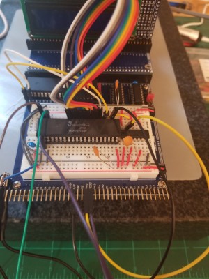
Here's everything hooked up:

Attachment:
20220702_152042.jpg
20220702_152042.jpg [ 3.45 MiB | Viewed 851 times ]


Getting it to do something is now simply a matter of programming some sane values into its 18 control registers. The HD6845 thinks of everything in terms of characters rather than dots or clocks, so setting up the registers with something approximately normal is not too tricky; I went with 100 characters per line, 80 characters visible, 26 lines per frame, 24 lines visible. There are a couple of extra registers that let you tweak exactly where the sync pulses fall within the blanking periods, which I'm sure will be useful for whenever I eventually actually hook it up to a CRT. For now, I just want to make sure the chip is working, and programmable through the VIA. So I fired it up, and after twiddling with with my oscilloscope and laboriously counting 80+ clock pulses, I did indeed find an HSYNC pulse right where it was supposed to be. 8)

Now I have to go do some math...

_________________
"The key is not to let the hardware sense any fear." - Radical Brad


Top
 Profile  
Reply with quote  
PostPosted: Thu Jul 07, 2022 9:11 pm 
Offline

Joined: Fri Mar 18, 2022 6:33 pm
Posts: 443
My Mouser order was delivered today, so I added the clock to my CRTC circuit. 13.5 MHz oscillators are Really Expensive (TM) for some reason, so I'm using a 27MHz one. It's hooked up to an 'AHCT161 to get /2, /4, /8, and /16 outputs. I'm using /2 (13.5MHz) as my NTSC dot clock, and /16 (which is 1/8th of /2) for my character clock - in other words, characters are 8 dots wide.

Attachment:
20220707_161836.jpg
20220707_161836.jpg [ 3.68 MiB | Viewed 793 times ]


The clocks look pretty bouncy. I added a bunch of decoupling caps, some 10uF smoothing caps, and some ground return wires, but nothing really helped. I'm guessing it's just due to being on breadboards.

Attachment:
20220707_161856.jpg
20220707_161856.jpg [ 3.35 MiB | Viewed 793 times ]


Then I did a little math (actually, I used this handy calculator: https://mrboot.de/mc6845.php, but what it spat out was pretty close to what I came up with by hand) and reprogrammed the CRTC registers. HSYNC and VSYNC are now looking pretty good!

Attachment:
20220707_164516.jpg
20220707_164516.jpg [ 2.96 MiB | Viewed 793 times ]

Attachment:
20220707_164502.jpg
20220707_164502.jpg [ 3.01 MiB | Viewed 793 times ]


As I've been pondering this circuit, I'm thinking that I'm going to have a serious address bus contention / clock domain crossing problem, thanks to trying to interface a fast modern MPU with an old slow peripheral IC. This is interesting since it's the opposite of the usual situation, but also kind of a pain. I think I will ramble more about that in a separate post.

_________________
"The key is not to let the hardware sense any fear." - Radical Brad


Top
 Profile  
Reply with quote  
PostPosted: Thu Jul 07, 2022 9:37 pm 
Offline

Joined: Tue Jul 05, 2005 7:08 pm
Posts: 994
Location: near Heidelberg, Germany
Are you sure the 6545 E input needs to connect to the inverted Phi2?

IIRC this should be the same as Phi2 to enable accessing register access to the CPU.

Also IIRC the video address lines are stable enough during phi2 low so you can use them as RAM address input.
I've done a design like this and the old Commodore PET use it the same way.

André

_________________
Author of the GeckOS multitasking operating system, the usb65 stack, designer of the Micro-PET and many more 6502 content: http://6502.org/users/andre/


Top
 Profile  
Reply with quote  
PostPosted: Thu Jul 07, 2022 10:11 pm 
Offline

Joined: Fri Mar 18, 2022 6:33 pm
Posts: 443
Hi Andre,

fachat wrote:
Are you sure the 6545 E input needs to connect to the inverted Phi2?


In fact, no. :) Although the data sheet suggests using the inverted system clock, the HD6845's memory refresh lines are clocked by the character clock (CLK), not by the E clock. Although it's not explicitly stated, the only way that using the inverted clock makes sense is if the character clock rate is the same as the system clock, so that the MPU has access to video ram on the first half of the cycle, and the CRTC has access to video ram on the second half of the cycle. This is one of the things I was planning to ramble about in a future post: Since the maximum E clock of the HD6845 is 2MHz, using the system clock as the E clock means my modern WDC6502 will be hobbled at 1/7th of its nominal speed. It almost seems like it would be better to tie the E clock to the character clock and set up a 6522 to do some asynchronous communication. I don't like the idea of losing direct access to video ram, but I also don't want to run in slow motion!

Which brings me to the other thing I was going to ramble about - I think it's a real shame that WDC doesn't offer something like the 6545 or 6560. It would be awfully nice to have a 14MHz version of this chip. I guess their market is geared towards embedded systems - where I can see there would not be much of a demand for CRTCs :D - rather than hobbyists like me.

_________________
"The key is not to let the hardware sense any fear." - Radical Brad


Top
 Profile  
Reply with quote  
PostPosted: Mon Jul 11, 2022 6:38 am 
Offline
User avatar

Joined: Sun Jun 30, 2013 10:26 pm
Posts: 1930
Location: Sacramento, CA, USA
Paganini wrote:
Code:
cmp    #$FF
bmi    etc

That makes my head hurt ... branch if the accumulator is [$7F .. $FE] ???

_________________
Got a kilobyte lying fallow in your 65xx's memory map? Sprinkle some VTL02C on it and see how it grows on you!

Mike B. (about me) (learning how to github)


Top
 Profile  
Reply with quote  
PostPosted: Mon Jul 11, 2022 12:39 pm 
Offline

Joined: Fri Mar 18, 2022 6:33 pm
Posts: 443
Hi Mike,

It just means branch if Bit 7 (the sign bit) is set. In this particular case, Bit 7 is the busy flag from the LCD; when it goes low the LCD is finished and ready for the next command. LDA sets the N bit automatically, so CMP #$FF is not needed, but the reference I was looking at at the time didn't make that clear; hence the question. :)

Edit: In this case, I should have said `PLA`, not `LDA.` The question was about how pulling from the stack affects the status register.

_________________
"The key is not to let the hardware sense any fear." - Radical Brad


Top
 Profile  
Reply with quote  
PostPosted: Mon Jul 11, 2022 2:06 pm 
Offline
User avatar

Joined: Thu Dec 11, 2008 1:28 pm
Posts: 10800
Location: England
Mike has a really good point here, though. That CMP #$FF is not doing what you want, even if it were needed. So you probably need to update your idea of how CMP works, or you might later get into trouble.

The way I think of it, CMP is a subtract which sets the flags but discards the result. So CMP #$FF will subtract FF. So, if you start with FF, you get zero, and so N and Z will be set(*). But according to your assumption, FF would have set N - not so!

(*) also C will be set. I find it easiest to try short sequences in a web-based emulator such as
https://skilldrick.github.io/easy6502/#first-program
or the venerable
https://www.masswerk.at/6502/
or the recent
http://calc6502.com/ia6502/main.html


Top
 Profile  
Reply with quote  
PostPosted: Mon Jul 11, 2022 8:24 pm 
Offline

Joined: Fri Mar 18, 2022 6:33 pm
Posts: 443
Oh ah, I see what you're saying. I think at that point I had not yet learned of the existence of the BIT instruction and thought every conditional branch had to have a CMP, unless the preceding instruction magically filled the status register. I'm kind of surprised that accidentally worked. When busy was high, %10000000 - %11111111 = 10000001, so the branch was taken. When busy was low, %00000000 - %11111111 = 1, so the branch was not taken. But that surely was not the logic I wanted to express! :lol:

Looking back from my lofty vantage point of 3 months in the future, I wonder why I was pulling anything off the stack in the first place. Even without BIT, all I had to do was LDA PORTA, BMI BUSY.

_________________
"The key is not to let the hardware sense any fear." - Radical Brad


Top
 Profile  
Reply with quote  
Display posts from previous:  Sort by  
Post new topic Reply to topic  [ 256 posts ]  Go to page Previous  1 ... 6, 7, 8, 9, 10, 11, 12 ... 18  Next

All times are UTC


Who is online

Users browsing this forum: No registered users and 1 guest


You cannot post new topics in this forum
You cannot reply to topics in this forum
You cannot edit your posts in this forum
You cannot delete your posts in this forum
You cannot post attachments in this forum

Search for:
Jump to: