6502.org Forum  Projects  Code  Documents  Tools  Forum
It is currently Thu May 02, 2024 8:19 am

All times are UTC


Post new topic Reply to topic  [ 256 posts ]  Go to page Previous  1 ... 7, 8, 9, 10, 11, 12, 13 ... 18  Next
Author Message
PostPosted: Mon Jul 11, 2022 8:46 pm 
Offline
User avatar

Joined: Fri Aug 30, 2002 1:09 am
Posts: 8429
Location: Southern California
This is from approximately the middle of the programming-tips page of the 6502 primer:

    An automatic compare-to-zero instruction is built into the following 65c02 instructions: LDA, LDX, LDY, INC, INX, INY, DEC, DEX, DEY, INA, DEA, AND, ORA, EOR, ASL, LSR, ROL, ROR, PLA, PLX, PLY, SBC, ADC, TAX, TXA, TAY, TYA, and TSX. This means that, for example, a CMP #0 after an LDA is redundant, a wasted instruction. A kitten somewhere dies every time you do that! :D The only time a 65c02 (CMOS) needs a compare-to-zero instruction after one of these is if you want to compare a register that was not involved in the previous instruction; for example,

    Code:
            DEY
            CPX  #0

    (Note the Y and the X are not the same register.) If you can spare a register to which you can transfer the one you want to test, you can save a byte with the transfer instead of a compare instruction. The example above, if the contents of A don't need to be kept, could be changed to:

    Code:
            DEY
            TXA

    and then you can branch on the N or Z flag which tell if X was negative or zero. The TXA isn't any faster (both TXA and CPX# take two clocks); but TXA takes only one byte, whereas the CPX #0 takes two bytes.

    The NMOS 6502 did have a bug in that the flags weren't always correct after a decimal-mode operation like ADC; so then you might have to follow it with the CMP #0 to get the N and Z flags right. It's best to just use the CMOS processor for all new builds.

If you want to just check bit 7 of PORTA (PA), you can use BIT PORTA and not involve or disturb the accumulator. Then do your BMI.

_________________
http://WilsonMinesCo.com/ lots of 6502 resources
The "second front page" is http://wilsonminesco.com/links.html .
What's an additional VIA among friends, anyhow?


Top
 Profile  
Reply with quote  
PostPosted: Mon Nov 21, 2022 12:11 pm 
Offline
User avatar

Joined: Tue Aug 11, 2020 3:45 am
Posts: 311
Location: A magnetic field
Paganini on Fri 17 Jun 2022 wrote:
If all else fails, I can always get one of those breadboard PCBs and just solder the working breadboard circuit onto it. :D


I was perplexed by breadboard PCBs and assumed that the ingenious Asians were filling a demand created by clueless newbies. I now think that I could have saved some effort 15 years ago if they were commonly available. Actually, I'm now perplexed that 0.1 inch breadboards have been available for more than 50 years but matching PCBs have only become popular after numerous incompatible stripboard variants.

_________________
Modules | Processors | Boards | Boxes | Beep, Beep! I'm a sheep!


Top
 Profile  
Reply with quote  
PostPosted: Mon Nov 21, 2022 2:46 pm 
Offline

Joined: Fri Mar 18, 2022 6:33 pm
Posts: 438
I don't know anything about the timeline of stripboard with power rails, but I recently came across this nifty guy:

https://www.amazon.com/gp/product/B0040 ... B1JT&psc=1

At $12, it's a bit pricy for one board, but I really like the layout.

_________________
"The key is not to let the hardware sense any fear." - Radical Brad


Top
 Profile  
Reply with quote  
PostPosted: Mon Nov 21, 2022 8:54 pm 
Offline
User avatar

Joined: Fri Aug 30, 2002 1:09 am
Posts: 8429
Location: Southern California
Sheep64 wrote:
Paganini on Fri 17 Jun 2022 wrote:
If all else fails, I can always get one of those breadboard PCBs and just solder the working breadboard circuit onto it. :D

I was perplexed by breadboard PCBs and assumed that the ingenious Asians were filling a demand created by clueless newbies. I now think that I could have saved some effort 15 years ago if they were commonly available. Actually, I'm now perplexed that 0.1 inch breadboards have been available for more than 50 years but matching PCBs have only become popular after numerous incompatible stripboard variants.

I've been using this Radio Shack solder-type breadboard for analog circuits for about 40 years:
Attachment:
RS_276-170.jpg
RS_276-170.jpg [ 25.79 KiB | Viewed 777 times ]

A nice thing about these is that you can get two or sometimes even three leads in one hole for dense analog circuits with lots of discrete components like 1/8W resistors and capacitors.

_________________
http://WilsonMinesCo.com/ lots of 6502 resources
The "second front page" is http://wilsonminesco.com/links.html .
What's an additional VIA among friends, anyhow?


Top
 Profile  
Reply with quote  
PostPosted: Fri Nov 25, 2022 7:14 pm 
Offline

Joined: Fri Mar 18, 2022 6:33 pm
Posts: 438
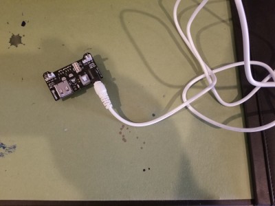
A few years ago when I first decided to get my feet wet I got one of those "ELEGO" "all the parts you'll ever need" kits from Amazon. Ever since then my breadboard projects have been powered either by a jumper wire from Blue April's backplane, or by one of these little guys:

Attachment:
20221125_133315.jpg
20221125_133315.jpg [ 3.44 MiB | Viewed 679 times ]


It runs off of a 9V wall wart and is jumper configurable for 3.3v or for 5v. It's OK - but it is kind of a pain, in that it lifts off the board at random times, and it also takes up quite a bit of board space. Around the same time I got that "ELEGO" kit, I got a Jameco breadboard, because they're supposed to be very nice. Well, they are, but sadly the little power doohickey pictured above won't fit on the Jameco power rails. So ever since then I've used a BusBoard breadboard (which is also pretty good) and the nice Jameco breadboard stayed in the box.

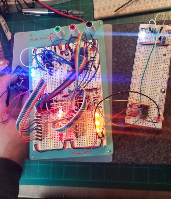
On a luthiery forum I sometimes read, one of the contemporary master luthiers says "it's a poor workman who blames his tools... because a good workman doesn't have bad tools!" So in that spirit I decided to upgrade my breadboard situation before returning to my video timing project. I got the cheapest aluminum backed breadboard I could find ($20 on Amazon), switched out its low quality Chinese breadboard with my nice Jameco one, upgraded its extremely flimsy banana jacks with some nicer ones (I also had to give it taller legs to make room for the new nice banana jacks!) and got a 5v switching wall wart for it.

Attachment:
20221125_113606.jpg
20221125_113606.jpg [ 3.79 MiB | Viewed 679 times ]


It seems that generating video timings from a ROM is well-trodden territory around here. As I started building, I discovered that George (gfoot) from right here on the 6502 forums had already done what I had in mind, and much more! I basically ended up duplicating cleanroom-style his "Simplest VGA circuit" https://hackaday.io/project/175434-worl ... ga-circuit. Mine's not quite identical, but it is close. Also, I ran into a few small problems and gave up the cleanroom idea and asked George some questions. Thanks for your help George!

I kind of like this slow-mo version (Slowest Video Card in the World?) with a bunch of LEDs I made for troubleshooting. The PCB on the left is a debounced button circuit for manually pulsing the clock. The spare breadboard on the right has a 555 timer circuit with a variable resistor so I can run it in bullet time, more or less.

Attachment:
20221125_120535.jpg
20221125_120535.jpg [ 1.72 MiB | Viewed 679 times ]


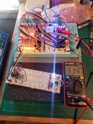
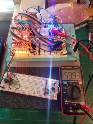
But, it's only useful if it actually produces correct timings:

Attachment:
20221125_121742.jpg
20221125_121742.jpg [ 4.01 MiB | Viewed 679 times ]

Attachment:
20221125_121755.jpg
20221125_121755.jpg [ 4.06 MiB | Viewed 679 times ]


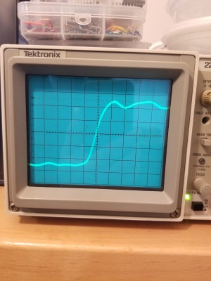
Here's the HSYNC signal at .05 uS x10 per division:

Attachment:
20221125_123036.jpg
20221125_123036.jpg [ 3.26 MiB | Viewed 679 times ]


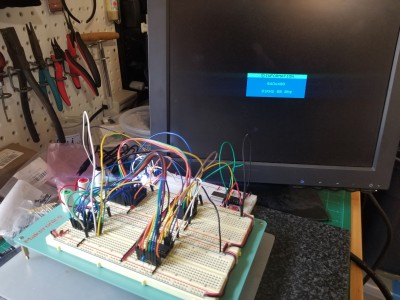
I think that's pretty good, especially given the length of the ground lead I had to use to get at the signal! I couldn't get my scope to trigger on VSYNC; I guess 60Hz is just too slow for it. Of course, the real question is not whether or not I think it's good, but whether a real monitor will accept it:

Attachment:
20221125_133149.jpg
20221125_133149.jpg [ 3.78 MiB | Viewed 679 times ]


I have to admit that, even though I'm reinventing the wheel here, at this point I did a very undignified happy dance. :D

_________________
"The key is not to let the hardware sense any fear." - Radical Brad


Top
 Profile  
Reply with quote  
PostPosted: Fri Nov 25, 2022 7:39 pm 
Offline
User avatar

Joined: Thu Dec 11, 2008 1:28 pm
Posts: 10793
Location: England
If it makes you dance, you must be having fun! That's the goal!


Top
 Profile  
Reply with quote  
PostPosted: Fri Nov 25, 2022 10:52 pm 
Offline

Joined: Sat Oct 09, 2021 11:21 am
Posts: 703
Location: Texas
Love seeing the sync signals come in great! Are you using a ROM for timing signals? Using the same down-counter that George was using (I believe that was what he was doing)? Plans for color signals? Is this going to attached to Blue April?

Sorry, lots of questions! Very good to see, great job :)

Chad


Top
 Profile  
Reply with quote  
PostPosted: Sat Nov 26, 2022 3:50 pm 
Offline

Joined: Fri Mar 18, 2022 6:33 pm
Posts: 438
Hi Chad! Yep, using a ROM for timing signals. I'm not that interested in color or bit-map graphics, I want a text terminal, so I have VBLANK and HBLANK in addition to HSYNC and VSYNC. The counters are 74HC590s, which I think is the same as George used.

I think, in the long run, I might give Blue April RS232 and connect to this over it. The reason is that the old CRTC chip I was playing with had a maximum system clock speed of 2MHz. Blue April normally runs at 8Mhz, and I think can probably do more. Limiting the system clock to 2Mhz in order to get video out of an old chip seemed kind of silly at that point. I would probably get better performance leaving the clock up, bit banging the video, and letting her do other stuff during the blanking periods. This is also not very appealing, so I thought, well, why not just have a dedicated video coprocessor? Can have a second 6502 that does all the video stuff, runs at whatever clock the old CRTC chip likes, and is just basically an old-school terminal. THEN I thought, if I'm going to go that far, I might as well ditch the CRTC and generate the timings myself. I'll learn more, and can do VGA instead of composite. :D

_________________
"The key is not to let the hardware sense any fear." - Radical Brad


Top
 Profile  
Reply with quote  
PostPosted: Sat Nov 26, 2022 8:46 pm 
Offline

Joined: Fri Mar 18, 2022 6:33 pm
Posts: 438
Tidied up a bit (don't need all those trouble LEDs now)! Also, switched to an M27C256 EPROM. I have a few of them laying around, and I've been wanting to do a project with them. Even though the Atmel EEPROM I used in the first build seemed to be doing fine with it's 150ns rating, my EPROMs are rated at 70ns. 8)

Attachment:
20221126_154129.jpg
20221126_154129.jpg [ 3.15 MiB | Viewed 572 times ]

_________________
"The key is not to let the hardware sense any fear." - Radical Brad


Top
 Profile  
Reply with quote  
PostPosted: Sat Nov 26, 2022 11:26 pm 
Offline

Joined: Sat Oct 09, 2021 11:21 am
Posts: 703
Location: Texas
Paganini wrote:
Hi Chad! Yep, using a ROM for timing signals. I'm not that interested in color or bit-map graphics, I want a text terminal, so I have VBLANK and HBLANK in addition to HSYNC and VSYNC. The counters are 74HC590s, which I think is the same as George used.


Very good goals. When you find a way to (quickly) use a character ROM, let me know! I am still puzzled as to how I could get an EEPROM or some such to run fast enough to be my character ROM.

Looks good! I'm happy to see you progress on this!

Chad


Top
 Profile  
Reply with quote  
PostPosted: Sun Nov 27, 2022 4:14 am 
Offline

Joined: Fri Mar 18, 2022 6:33 pm
Posts: 438
Just a brief update and a reply to Chad!

I did some resistor math this afternoon, made a little resistor network, and got my little display to emit a passable amber! This means my HBLANK and VBLANK signals are good, because they are gating the RGB output signal.

Attachment:
20221126_213301.jpg
20221126_213301.jpg [ 3.52 MiB | Viewed 547 times ]


Then, even though I said I'm not interested in color, I got rid of the resistor network, put in some variable resistors, and had fun dialing in some different colors! I guess I'm interested in having exactly one color! :D

Attachment:
20221126_215634.jpg
20221126_215634.jpg [ 3.27 MiB | Viewed 547 times ]


sburrow wrote:
When you find a way to (quickly) use a character ROM, let me know! I am still puzzled as to how I could get an EEPROM or some such to run fast enough to be my character ROM.


I haven't tried it yet, but I don't think it should be a problem. The character clock for this project will be approximately πMHz (25.175 pixel clock / 8). In theory, once every character clock the ROM will spit out 8 bits (one line) of character data, which is absorbed by a 165 PISO shift register, which in turn will squirt pixels to the screen at the pixel clock rate. I'm more worried about the timing of the shift register. The 165 has an asynchronous parallel load, and must hold all 8 bits to shift them out. In other words, I'll have to shift out the last bit then shift in the next byte before it's time to shift out the first bit of the next byte. That's a pretty small target!

_________________
"The key is not to let the hardware sense any fear." - Radical Brad


Top
 Profile  
Reply with quote  
PostPosted: Sun Nov 27, 2022 7:22 pm 
Offline

Joined: Sat Oct 09, 2021 11:21 am
Posts: 703
Location: Texas
Paganini wrote:
Then, even though I said I'm not interested in color, I got rid of the resistor network, put in some variable resistors, and had fun dialing in some different colors! I guess I'm interested in having exactly one color! :D

I haven't tried it yet, but I don't think it should be a problem. The character clock for this project will be approximately πMHz (25.175 pixel clock / 8). In theory, once every character clock the ROM will spit out 8 bits (one line) of character data, which is absorbed by a 165 PISO shift register, which in turn will squirt pixels to the screen at the pixel clock rate. I'm more worried about the timing of the shift register. The 165 has an asynchronous parallel load, and must hold all 8 bits to shift them out. In other words, I'll have to shift out the last bit then shift in the next byte before it's time to shift out the first bit of the next byte. That's a pretty small target!


I put pots on my last monochrome build as well. It is neat to change to whatever color you want at the time.

As far as the shift register, I use a '166 instead of a '165. But they look similar. As far as I can tell, you drive /PE low, and THEN you rise the CLK line to actually parallel load. Sync loading, not async.

OH I see, yes, the '165 is async loading, but the '166 is sync loading. I would recommend the '166 instead.

Glad things are working out so quickly!

Chad


Top
 Profile  
Reply with quote  
PostPosted: Tue Nov 29, 2022 10:50 pm 
Offline

Joined: Fri Mar 18, 2022 6:33 pm
Posts: 438
Another quick update: not too many improvements this evening, but I did add a latch and a 74HC08 to the HBLANK / VBLANK signals, so I have an actual output stage instead of a bunch of random flying wires! Chad, you were absolutely right about the synchronous shift register; I have some `166s on order from Digikey. I get weird results with the `165. The load timing is tooo fussy.

For testing purposes, I just connected the output stage to the `163 I'm using as a prescaler. It all worked as expected. It's a little hard to capture these in photographs, but I think this might be the most "useful" one:

Attachment:
20221129_173316.jpg
20221129_173316.jpg [ 3.69 MiB | Viewed 484 times ]


Each "bar" is 8 pixels wide, and there are 40 "on" bars and 40 "off" bars, so that is basically a template for 80 column text.

_________________
"The key is not to let the hardware sense any fear." - Radical Brad


Top
 Profile  
Reply with quote  
PostPosted: Thu Dec 01, 2022 2:45 pm 
Offline

Joined: Sat Oct 09, 2021 11:21 am
Posts: 703
Location: Texas
Paganini wrote:
Each "bar" is 8 pixels wide, and there are 40 "on" bars and 40 "off" bars, so that is basically a template for 80 column text.


Cool! Would like to see your test of that Character ROM with that setup. Even random garbage or repeating patterns would be a good sign if it's *really* going to work (I'm super scared so I'll let you try first!).

I found 80 columns is very nice to use. I have that on most of my builds. On my next one I'm considering only a 40-column mode to save chips and logic and stuff.

How are you going to interface the screen RAM (be it characters or bitmap) with your CPU RAM? You said Blue April is running at 8 MHz, which is not a direct division of the 25.175 MHz. You mentioned a serial connection, so would you use a ACIA or bit bang from a VIA?

Glad you are making progress!

Chad


Top
 Profile  
Reply with quote  
PostPosted: Thu Dec 01, 2022 4:32 pm 
Offline

Joined: Fri Mar 18, 2022 6:33 pm
Posts: 438
Well, the "character ROM" is still a bit-map file on my Mac, sooooo... :) I did plug in a random ROM I had laying around that I happened to know had some 6502 machine code on it, hoping to get some random junk. I did not get any random junk, thanks to the many errors between the ROM and the screen. I have slowly been working my way back up the chain, fixing things as I go. I've almost got back to the ROM! Getting a successful output from any memory means the parallel / serial conversion must be working, and - it isn't. Yet!

Chad wrote:
How are you going to interface the screen RAM (be it characters or bitmap) with your CPU RAM? You said Blue April is running at 8 MHz, which is not a direct division of the 25.175 MHz. You mentioned a serial connection, so would you use a ACIA or bit bang from a VIA?


I think I would like to try the ACIA. I don't have one, and it seems like a useful chip to get to know. Garth has an RS232 primer that I haven't read yet, but looks comprehensive!

_________________
"The key is not to let the hardware sense any fear." - Radical Brad


Top
 Profile  
Reply with quote  
Display posts from previous:  Sort by  
Post new topic Reply to topic  [ 256 posts ]  Go to page Previous  1 ... 7, 8, 9, 10, 11, 12, 13 ... 18  Next

All times are UTC


Who is online

Users browsing this forum: No registered users and 15 guests


You cannot post new topics in this forum
You cannot reply to topics in this forum
You cannot edit your posts in this forum
You cannot delete your posts in this forum
You cannot post attachments in this forum

Search for:
Jump to: