6502.org Forum  Projects  Code  Documents  Tools  Forum
It is currently Mon May 06, 2024 9:43 pm

All times are UTC


Post new topic Reply to topic  [ 126 posts ]  Go to page Previous  1, 2, 3, 4, 5 ... 9  Next
Author Message
PostPosted: Mon Oct 25, 2021 8:29 pm 
Offline
User avatar

Joined: Thu May 28, 2009 9:46 pm
Posts: 8175
Location: Midwestern USA
akohlbecker wrote:
I'm curious to hear what the problems are with using RDY for wait states?

The two linked topics go into considerable detail but in a nutshell, anything in a 65C816 system slaved to Ø2 will not behave as expected when RDY is driven low. While the MPU's internal clock will stop in the high (data) phase, that has no effect beyond the MPU. Other devices that are gated with Ø2 or its inversion, or controlled by logic that includes Ø2 as a qualifier, will synchronously oscillate between states. This is particularly a problem with the bank bits latch, but that is not the only possible area of trouble. The first of the two topics I linked describes three different scenarios, two of which are not unique to the 65C816.

_________________
x86?  We ain't got no x86.  We don't NEED no stinking x86!


Top
 Profile  
Reply with quote  
PostPosted: Mon Oct 25, 2021 9:26 pm 
Offline
User avatar

Joined: Sat Jul 24, 2021 1:37 pm
Posts: 282
Thank you for the details! Making sure the latch and the buffer are in the correct state while asserting RDY was the subject of the last few episodes, you can see how I handled it in the circuit I posted above.

I haven't talked yet about my plans for chip selects and read/write pulses but they work with RDY as well (chip selects being statically mapped to addresses and pulses being gated with RDY).

I agree that some care needs to be taken especially around timings but it is not that bad.

_________________
BB816 Computer YouTube series


Top
 Profile  
Reply with quote  
PostPosted: Tue Oct 26, 2021 2:11 am 
Offline
User avatar

Joined: Thu May 28, 2009 9:46 pm
Posts: 8175
Location: Midwestern USA
akohlbecker wrote:
Thank you for the details! Making sure the latch and the buffer are in the correct state while asserting RDY was the subject of the last few episodes, you can see how I handled it in the circuit I posted above.

I haven't talked yet about my plans for chip selects and read/write pulses but they work with RDY as well (chip selects being statically mapped to addresses and pulses being gated with RDY).

I agree that some care needs to be taken especially around timings but it is not that bad.

In the 65C816, I generally view RDY as an artifact that was included to support 65C02 emulation mode (RDY is close to useless on the NMOS processors—the MPU won't stop during a write cycle). There are several aspects of the 816's hardware that exist due to Apple have a lot of say-so in the MPU's design. For example, the 816's bus behavior is that of the NMOS 6502, a "feature" that was demanded by Apple so the 816 would work with their idiosyncratic disk drive controller (which was not one of Wozniak's shining examples of electronics design, in my opinion). Bill Mensch thoughtfully include VDA and VPA so designers who weren't relying on NMOS-style dummy bus accesses had a way to prevent them from affecting the hardware.

As an output, RDY could be useful, since it gets driven low while the 816 is executing WAI. In a preemptive, multitasking kernel driving a system with the right sort of glue logic, a process could relinquish its time quantum by executing WAI, which would then cause the glue logic to immediately trigger an IRQ to bring about a context switch.

I used clock-stretching in my POC V1.2, 1.3 and 2.0 units. RDY is unused in all of them.

_________________
x86?  We ain't got no x86.  We don't NEED no stinking x86!


Top
 Profile  
Reply with quote  
PostPosted: Tue Oct 26, 2021 2:21 pm 
Offline
User avatar

Joined: Mon Aug 30, 2021 11:52 am
Posts: 258
Location: South Africa
BigDumbDinosaur wrote:
...before you go off on a tangent with a FIFO and use a battleship to sink a rowboat.
But what if I want to use a battleship to sink rowboats, that's normal right. Right? :wink:

Although I don't want to hi-jack Adrien's thread too much but I did misunderstand what you meant by extended memory. I thought you meant meant an SD card or slow ROM or even a UART or something. My actual address decoding is so ridiculously ridiculous that I need to test real timings before I post anything to this forum. (my still unplanned plan with the FIFO is to use it for keyboards, mouses, game-controllers etc...).


Top
 Profile  
Reply with quote  
PostPosted: Tue Oct 26, 2021 3:35 pm 
Offline
User avatar

Joined: Thu May 28, 2009 9:46 pm
Posts: 8175
Location: Midwestern USA
AndrewP wrote:
BigDumbDinosaur wrote:
...before you go off on a tangent with a FIFO and use a battleship to sink a rowboat.
But what if I want to use a battleship to sink rowboats, that's normal right. Right? :wink:

Well, I was in the Navy and most of the time, we'd use the right-sized weapon for the job. But, once in a while, a certain amount of overkill got into the picture. :D

BTW, the muzzle blast from just one of a battleship's 16 inch guns is so powerful it would literally blow a small boat out of the water without the projectile having to hit anything.

Attachment:
uss_iowa_bb-61_pr.jpg
uss_iowa_bb-61_pr.jpg [ 1.77 MiB | Viewed 1179 times ]

Quote:
Although I don't want to hi-jack Adrien's thread too much but I did misunderstand what you meant by extended memory. I thought you meant meant an SD card or slow ROM or even a UART or something. My actual address decoding is so ridiculously ridiculous that I need to test real timings before I post anything to this forum. (my still unplanned plan with the FIFO is to use it for keyboards, mouses, game-controllers etc...).

For clarity in my 65C816 designs, I use the term "basic RAM" to refer to bank $00 RAM below the I/O block, "high RAM" to refer to any bank $00 RAM that is above the I/O block, and "extended RAM" to refer to RAM that is not in bank $00. If a 65C816 system has extended RAM it is implied that bank latching hardware is present and so are the foibles associated with using RDY to wait-state the MPU.

_________________
x86?  We ain't got no x86.  We don't NEED no stinking x86!


Top
 Profile  
Reply with quote  
PostPosted: Tue Nov 16, 2021 8:48 pm 
Offline
User avatar

Joined: Sat Jul 24, 2021 1:37 pm
Posts: 282
Episode 8 is online!

In this episode, I start building the clock module. I have bigger goals for this module than just running my 65C816 as I plan to re-use this design elsewhere, so you could say this will be a mini-series within the series:

  • 3 clocks: fast, slow, pulse
    • Fast: from ~1MHz to 14MHz via DIP switch (progressively ramp up the speed and reach 14Mhz)
    • Slow: from 0.5Hz to 500Hz via potentiometer (for blinking lights!)
    • Pulse: one clock pulse per button press (for single stepping)
  • 2 selection buttons: mode (free running / pulse), speed (fast / slow)
  • Clean clock switching (no switching in the middle of a cycle)
  • HALT line (stops the clock until RESET)
  • BRK line (switches to pulse mode)
  • Power up behaviour configurable via DIP switch (=which mode and speed on power up)
  • Output stage is a flip flop
    • Clean 50/50 duty cycle
    • Synchronised ~CLK

In this episode I also discuss logic family choice (between HC, AC, AHC as a clock driver specifically), and talk a bit about hardware switch de-bouncing.

As always, hopeful that you find this interesting!

_________________
BB816 Computer YouTube series


Top
 Profile  
Reply with quote  
PostPosted: Thu Nov 18, 2021 1:50 pm 
Offline
User avatar

Joined: Thu Dec 11, 2008 1:28 pm
Posts: 10799
Location: England
Clean clock switching is a good thing to have mastered!


Top
 Profile  
Reply with quote  
PostPosted: Wed Nov 24, 2021 11:04 pm 
Offline
User avatar

Joined: Sat Jul 24, 2021 1:37 pm
Posts: 282
BigEd wrote:
Clean clock switching is a good thing to have mastered!


Thanks! I think I have a pretty good design, coming in episode 11.

In the meantime, I released Episode 9 last week, which goes further into the clock module. I added a multiplexer to select between the clocks (not in a clean way yet), and implemented the fast clock divider. Had some issues with the fast clock when trying to go to 14MHz (and running my counter at 28MHz, which was a bit too high), so I'll need to go back to the drawing board and I stayed at 10Mhz for now.

This is what the clock looks like now

Attachment:
clock-Clock.png
clock-Clock.png [ 297.52 KiB | Viewed 1044 times ]

_________________
BB816 Computer YouTube series


Top
 Profile  
Reply with quote  
PostPosted: Thu Nov 25, 2021 6:30 am 
Offline
User avatar

Joined: Thu May 28, 2009 9:46 pm
Posts: 8175
Location: Midwestern USA
akohlbecker wrote:
This is what the clock looks like now

WDC specifies that the rise/fall time for the Ø2 clock should not exceed 5ns. That's generally not achievable with 74HC logic.

_________________
x86?  We ain't got no x86.  We don't NEED no stinking x86!


Top
 Profile  
Reply with quote  
PostPosted: Thu Nov 25, 2021 10:13 am 
Offline
User avatar

Joined: Sat Jul 24, 2021 1:37 pm
Posts: 282
BigDumbDinosaur wrote:
akohlbecker wrote:
This is what the clock looks like now

WDC specifies that the rise/fall time for the Ø2 clock should not exceed 5ns. That's generally not achievable with 74HC logic.


Interesting, I was investigating this number and found this AHC/AHCT Designer’s Guide from TI that shows the slew rates of HC, AC and AHC gates:

Attachment:
Screenshot 2021-11-25 at 11.11.09.png
Screenshot 2021-11-25 at 11.11.09.png [ 251.11 KiB | Viewed 1023 times ]


Based on these numbers and assuming a 10% to 90% rise I'm getting the following rise/fall times, which shows HC being ≤ 5ns.

Attachment:
Screenshot 2021-11-25 at 11.12.18.png
Screenshot 2021-11-25 at 11.12.18.png [ 297.28 KiB | Viewed 1023 times ]


Do you have another source I could look at that point to the contrary?

_________________
BB816 Computer YouTube series


Top
 Profile  
Reply with quote  
PostPosted: Thu Nov 25, 2021 10:45 am 
Offline
User avatar

Joined: Fri Aug 30, 2002 1:09 am
Posts: 8432
Location: Southern California
They seem to be tunnel-visioned on the '244 and '245. If you look at their data sheet for the 74HC74 (which you're using in your clock circuit), table 6.6, you'll see a max transition time of 13ns @ 6V and 25°C, up to 22ns @ 4.5V and -55°C to 125°C, both with a load capacitance of 50pF which is probably in the ballpark for what you'll be driving with it. It might work, but it's definitely not guaranteed to.

_________________
http://WilsonMinesCo.com/ lots of 6502 resources
The "second front page" is http://wilsonminesco.com/links.html .
What's an additional VIA among friends, anyhow?


Top
 Profile  
Reply with quote  
PostPosted: Thu Nov 25, 2021 7:19 pm 
Offline
User avatar

Joined: Thu May 28, 2009 9:46 pm
Posts: 8175
Location: Midwestern USA
akohlbecker wrote:
Based on these numbers and assuming a 10% to 90% rise I'm getting the following rise/fall times, which shows HC being ≤ 5ns.

As Garth said, TI used a single piece of logic (the '244) as an (atypical) example. The slew rates they tabulate in that graphic don't agree with the curves and in the case of 74HC, I know from observation and experience that a slew rate of ~5ns rail-to-rail not attainable in a practical application.

Although I mostly recommend the use of 74AHC logic with new builds—the prop times are comparable to 74AC, but slew rates are less aggressive, the clock generator flip-flop is an exception—74AC continues to be my choice there. Some series resistance between the flop's outputs and the rest of the circuit can mitigate ringing, which may be a significant problem on a breadboard. I've found 100-120 ohms is usually sufficient. A pair of fast Schottky diodes on the outputs may also help suppress ringing, although resorting to that technique usually isn't necessary on a well-designed PCB.

_________________
x86?  We ain't got no x86.  We don't NEED no stinking x86!


Top
 Profile  
Reply with quote  
PostPosted: Tue Dec 07, 2021 9:29 pm 
Offline
User avatar

Joined: Sat Jul 24, 2021 1:37 pm
Posts: 282
GARTHWILSON wrote:
They seem to be tunnel-visioned on the '244 and '245. If you look at their data sheet for the 74HC74 (which you're using in your clock circuit), table 6.6, you'll see a max transition time of 13ns @ 6V and 25°C, up to 22ns @ 4.5V and -55°C to 125°C, both with a load capacitance of 50pF which is probably in the ballpark for what you'll be driving with it. It might work, but it's definitely not guaranteed to.


Do you think different gates in the same family can have varying output characteristics? I was assuming they didn't.
Interesting point about that transition time. I've since then switched to a 74HC151 as output driver but the figure is comparable. I might have to go to a 74AC151 then, even though that one doesn't have a published transition time figure...

BigDumbDinosaur wrote:
akohlbecker wrote:
Based on these numbers and assuming a 10% to 90% rise I'm getting the following rise/fall times, which shows HC being ≤ 5ns.

As Garth said, TI used a single piece of logic (the '244) as an (atypical) example. The slew rates they tabulate in that graphic don't agree with the curves and in the case of 74HC, I know from observation and experience that a slew rate of ~5ns rail-to-rail not attainable in a practical application.

Although I mostly recommend the use of 74AHC logic with new builds—the prop times are comparable to 74AC, but slew rates are less aggressive, the clock generator flip-flop is an exception—74AC continues to be my choice there. Some series resistance between the flop's outputs and the rest of the circuit can mitigate ringing, which may be a significant problem on a breadboard. I've found 100-120 ohms is usually sufficient. A pair of fast Schottky diodes on the outputs may also help suppress ringing, although resorting to that technique usually isn't necessary on a well-designed PCB.


Good suggestion to add series termination

_________________
BB816 Computer YouTube series


Top
 Profile  
Reply with quote  
PostPosted: Tue Dec 07, 2021 9:38 pm 
Offline
User avatar

Joined: Sat Jul 24, 2021 1:37 pm
Posts: 282
Ok, I need to be more diligent about posting updates here as I publish my videos, I'm two episodes behind.

In Episode 10 - Power-up Reset I build a power-up circuit using a MAX705. Even though I used a DS1813 in my 6502 build, I like the MAX705 here for its watchdog, and separate manual reset input.
I also had to make sure that reset pulses would be registered by the CPU even if I'm running with a slow or manual clock. For that I chained the reset through 3 flip flops, to ensure it stays low for at least 2 full clock cycles.

Here is the final reset circuit:

Attachment:
reset-Reset.png
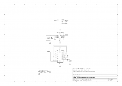
reset-Reset.png [ 175.74 KiB | Viewed 935 times ]


Next, in Episode 11 - Clock Module #3, I went back to the clock circuit and added glitch-free clock switching. By relying on the property that my clocks have vastly different frequencies, I'm able to ensure I always switch when a low-cycle of the destination clock begins and overlaps with a low cycle of the active clock. For that, I used a chain of negative edge triggered JK flip flops. I also had to change my output stage to a 74HC151 multiplexer, which is nice because it keeps the inverted output I had on the 74HC74

I also added a dip switch to select which clock mode and speed the circuit boots in on power up, so I can change it based on what I'm doing (hardware, software...)

Here is the current clock circuit

Attachment:
clock-Clock.png
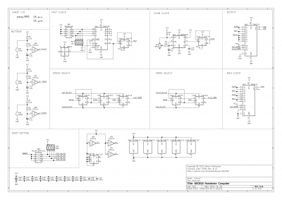
clock-Clock.png [ 430.41 KiB | Viewed 935 times ]


Next episode will be about starting up the CPU (finally, yay!) using a NOP generator.

_________________
BB816 Computer YouTube series


Top
 Profile  
Reply with quote  
PostPosted: Wed Dec 08, 2021 1:55 pm 
Offline
User avatar

Joined: Sat Jul 24, 2021 1:37 pm
Posts: 282
I have done some measurements on rise times, to compare a 74HCT151, 74AC151 and 74AC151 + 100 ohms series termination. My oscilloscope might not be good enough for this measurement (100MHz bandwidth), so take this with a grain of salt:

Attachment:
photo_2021-12-08 14.54.24.jpeg
photo_2021-12-08 14.54.24.jpeg [ 209.35 KiB | Viewed 907 times ]


Attachment:
File comment: 74HCT151
SDS00010.png
SDS00010.png [ 23.5 KiB | Viewed 907 times ]


Attachment:
File comment: 74AC151
SDS00009.png
SDS00009.png [ 23.58 KiB | Viewed 907 times ]


Attachment:
File comment: 74AC151 + 100 ohms termination
SDS00008.png
SDS00008.png [ 23.65 KiB | Viewed 907 times ]


Looks like switching to AC reduces the rise time a bit (14ns->10ns) but then adding termination increases it (10ns->20ns).
How much should I trust these measurements? Probably not much based on the bandwidth of my oscilloscope and the fact that this is on the breadboard?

_________________
BB816 Computer YouTube series


Top
 Profile  
Reply with quote  
Display posts from previous:  Sort by  
Post new topic Reply to topic  [ 126 posts ]  Go to page Previous  1, 2, 3, 4, 5 ... 9  Next

All times are UTC


Who is online

Users browsing this forum: No registered users and 9 guests


You cannot post new topics in this forum
You cannot reply to topics in this forum
You cannot edit your posts in this forum
You cannot delete your posts in this forum
You cannot post attachments in this forum

Search for:
Jump to: