6502.org Forum  Projects  Code  Documents  Tools  Forum
It is currently Mon Apr 29, 2024 9:04 am

All times are UTC


Post new topic Reply to topic  [ 30 posts ]  Go to page 1, 2  Next
Author Message
 Post subject: 6525 dissection
PostPosted: Mon Jan 31, 2022 11:10 am 
Offline
User avatar

Joined: Fri Nov 09, 2012 5:54 pm
Posts: 1392
//Previos thread: 8726 dissection.

This thread is about a transistor level dissection of the 6525 TPI (or TIA) Tri_Port Interface Adapter,
brought to you by Frank Wolf and ttlworks.

Basically, 6525 is "the MOS\CSG answer" to the Intel 8255,
except that in the 6525 the direction of the I\O ports can be set at Bit level,
and that the 6525 also contains a 5 level priority interrput controller.


6525 was used by Commodore in the ill-fated CBM-II series of computers (1982..1984),
in the 1551 floppy drive (1984..1986),
in the Magic Voice Speech Module (1984..1984),
in the Amiga A570 CD_ROM drive (released in 1992),
and in the CDTV (Amiga 500 plus CD_ROM drive, released in 1991).

Datasheets:
6525 Tri-Port Interface Adapter (TIA) (Undated)
6525 Tri-Port Interface Adapter (TIA) (Preliminary, Nov. 1980)
6525 Tri-Port Interface Adapter (TIA) (Preliminary, Feb. 1981)

;---

6525 has two modes of operation.

Mode 0: three I\O ports: Port A, Port B, Port C.
Each port has a register for data read/write plus another register for setting the direction of the related port pins.
No bells, no whistles.

Mode 1: two I\O ports: Port A (with read handshake), Port B (with write handshake).
Plus a 5 level priority interrupt controller.
The Port C pins are used for the handshake signals, and for the interrupt controller.
Also, the Port C registers now have a different function, mostly related to the interrupt controller.

The mode is selected with the MS Bit, that's Control Register Bit 0.

;---

A related chip seems to be the 6523,
which appears to be "something like a 6525 stuck in mode 0".

;---

Like the 6702 SuperPET dongle chip, 6525 and 6523 have no PHI2 pin,
so prepare to see a lot of edge detectors making creative use of gate delays.

Note:
For consistence with Frank's notation, low_active signals are named foo#, not /foo.

Orientation for all the chip pictures: D6 pad is North.


Top
 Profile  
Reply with quote  
 Post subject: Re: 6525 dissection
PostPosted: Mon Jan 31, 2022 11:11 am 
Offline
User avatar

Joined: Fri Nov 09, 2012 5:54 pm
Posts: 1392
Eagle 6.4 schematics for my schematic pictures in this thread,
just in case if somebody needs them.

Note: KiCad is supposed to be able to import these schematics,
unfortunately it doesn't seem to be possible to disable the layers 'name' and 'value' in KiCad schematics,
so making my schematics look nice and clean in KiCad will require some work, sorry.

Attachment:
6525r3_dissect_schematics.zip [373.98 KiB]
Downloaded 41 times


Top
 Profile  
Reply with quote  
 Post subject: Re: 6525 dissection
PostPosted: Mon Jan 31, 2022 11:12 am 
Offline
User avatar

Joined: Fri Nov 09, 2012 5:54 pm
Posts: 1392
A picture of the 6525 silicon, with the interesting areas marked.

Attachment:
6525r3_orientation.png
6525r3_orientation.png [ 157.77 KiB | Viewed 1009 times ]


Just as a reference, another picture of the 6525 silicon without the markings.

Attachment:
6525r3_small.png
6525r3_small.png [ 934.34 KiB | Viewed 1009 times ]


Top
 Profile  
Reply with quote  
 Post subject: Re: 6525 dissection
PostPosted: Mon Jan 31, 2022 11:14 am 
Offline
User avatar

Joined: Fri Nov 09, 2012 5:54 pm
Posts: 1392
6525 cheat sheet:

Attachment:
6525_0_cheatsheet.png
6525_0_cheatsheet.png [ 613.87 KiB | Viewed 1009 times ]


Now for a short overview of the registers,
and for a simplified block diagram about how the interrupt stuff is supposed to work.

//Port A, Port B handshake is described later in the text.

Attachment:
6525_0_int.png
6525_0_int.png [ 111.86 KiB | Viewed 1009 times ]


Port C pins PC0..4 are the interrupt inputs I0..4, where I0 has lowest priority, and I4 has highest priority.
I0..2 trigger on falling edge.
I3..I4 can be configurated to trigger on rising/falling edge.
//I3 and I4 edge detectors also happen to be the inputs for the Port A, Port B handshake logic.

;---

Now to dive into the Port C I\O logic block, PC0..4 (in mode 1).

I'm just describing the PC0 logic, because PC0..4 have identical chip layout.
I0 goes through an XOR gate (which is intended to be used for selecting edge polarity),
then goes into a falling edge detector, which sets a RS flipflop named "the INT0 interrupt latch"
when detecting a falling edge.
;
Note, that the XOR gate is present in the PC0..PC4 circuitry.
For PC0..2, the XOR input for selecting edge polarity is connected to GND.
For PC3..4, the XOR inputs are fed by the Control Register, namely the Bits IE3,IE4.

When writing the Port C data register, binary '0' clears the related INT latch after the write.
Also, an INT latch is cleared after pushing the interrupt stack when the related INT interrupt was acknowledged by AIR0..4.

Reading the Port C data register gives out the status of the INT0..4 latches in Bit 0..4,
Bit 5..7 just show what's on the PC5..7 pins.
That's IRQ# (low_active interrupt output of the 6525) in Bit 5,
CA (Port A handshake output) in Bit 6,
CB (Port B handshake output) in Bit 7.
//Note, that in mode 1, PC5..7 are "open collector" outputs switching to GND, which require an external pullup resistor.

Bit 0..4 of the Port C direction register is used for masking/enabling the interrupts.
Means the INT0..4 latches only generate a INT0..4 interrupt if the related Bit in the Port C direction register is '1'.
//Actally, INT0..4# are low_active, but we are getting there later.

;...

If interrupt priority is not enabled (IP=0, that's Control Register Bit 1), the rest is quite simple.
Because then what's on top of the interrupt stack is getting ignored by the interrupt logic.

"16) interrupt capture register" contains five RS flipflops, INT0..4 sets the related RS flipflop.
If (at least) one of the flipflops is set, the flipflops ignore further changes on INT0..4 until the flipflops are cleared again.
The outputs of these flipflops are on AIR0..4, and can be sensed by reading AIR (active interrupt register).

If a flipflop is set in the "16) interrupt capture register",
this sets the IRQ RS flipflop which pulls IRQ# low (PC5 pin of the chip).

The interrupt service routine reads AIR at the start to determine the interrupt source,
the AIR read clears the INT latches in the PC0..4 I\O logic that were detected in the "interrupt capture register",
also the AIR read clears the "interrupt capture register" if none of the INT0..4 signals was active.

If the INT0..4 signals are not active, the IRQ flipflop is cleared after an AIR read.

Since we are not using the interrupt stack, it's not really necessary to write AIR at the end of the interrupt service routine.

;...

If interrupt priority is enabled (IP=1),
"17) interrupt priority in" compares the priority level of the INT0..4 signals with what's on top of the interrupt stack:
An active INT0..4 signal needs to have at least the priority of what's on top of the interrupt stack
to set a RS flipflop in the "interrupt capture register".

Also, "15) interrupt priority out" makes sure that only the output with the highest priority of the "interrupt capture register"
shows up on AIR0..4 to be pushed on the interrupt stack and/or sensed by reading AIR.

When the interrupt service routine reads AIR at the start,
only _one_ INT latch in the PC0..4 I\O logic is cleared according to the active AIR0..4 signal.
Also, the AIR read pushes AIR0..4 on the interrupt stack.
//INT0 has the lowest priority, so the interrupt stack only pushes INT1..4.

The IRQ RS flipflop just works like described up in the text.

At the end of the interrupt service routine, AIR is written,
what popps the interrupt stack, clearing the bottom of the stack to $00.


Top
 Profile  
Reply with quote  
 Post subject: Re: 6525 dissection
PostPosted: Mon Jan 31, 2022 11:15 am 
Offline
User avatar

Joined: Fri Nov 09, 2012 5:54 pm
Posts: 1392
1) CS //the logic "close to the CS# pad, that is.

1W/R# is the inverted signal from the R/W# pad, generated in R/W".

We have a NOR gate with push/pull output, fed by the low_active signal CSin# from the CS# pad, and by and 1W/R#.
The output of the NOR goes through a non_inverting super buffer, which gives out the high_active READ signal.

READ is high, if CS# is low and R/W# is high. //when the CPU reads a 6525 register.

The READ signal goes into "6) address decoder".
Also, the READ signal enables the D0..7 output drivers, which give out the internal D0..7io data bus on the external D0..7 data bus.
//see "4) D7"

Attachment:
si6525_1_cs.png
si6525_1_cs.png [ 22.76 KiB | Viewed 1009 times ]

Attachment:
6525_1_cs.png
6525_1_cs.png [ 30.26 KiB | Viewed 1009 times ]


Last edited by ttlworks on Mon Jan 31, 2022 11:17 am, edited 1 time in total.

Top
 Profile  
Reply with quote  
 Post subject: Re: 6525 dissection
PostPosted: Mon Jan 31, 2022 11:16 am 
Offline
User avatar

Joined: Fri Nov 09, 2012 5:54 pm
Posts: 1392
2) R/W

The signal from the R/W# pad goes through an inverting super buffer and becomes 1W/R#.
Means: when R/W is low, 1W/R# is high.

1W/R# goes to "1) CS", also it goes through a non_inverting super buffer and becomes W/R#.
W/R# goes into "6) address decoder".

;...

Also, we have a three input NOR gate with push/pull output, feeding an inverting super buffer,
which gives out the low_active WRITE# signal.

1W/R# goes through three inverters, and into said NOR gate.
Also, said NOR gate is fed with R/W# from the R/W# pad, and with CSin# from the CS# pad.

If the CPU writes a 6525 register with CS# low and R/W# low, WRITE# goes low.
But WRITE# responds to the falling edge of R/W# with some delay (4 gates, maybe).

I think it was built that way to prevent timing problems:
if the external bus is shared between the CPU (at PHI2 high) and something like a VIC-II (at PHI2 low),
R/W# might not be valid/stable at the rising edge of PHI2.

WRITE# goes into "6) address decoder".
Also, WRITE# enables the D0..7 input buffers, which place the external data bus D0..7 on the internal data bus D0..7io.
//see "4) D7"

Attachment:
si6525_2_rw.png
si6525_2_rw.png [ 34.41 KiB | Viewed 1009 times ]

Attachment:
6525_2_rw.png
6525_2_rw.png [ 77.42 KiB | Viewed 1009 times ]


Top
 Profile  
Reply with quote  
 Post subject: Re: 6525 dissection
PostPosted: Mon Jan 31, 2022 11:19 am 
Offline
User avatar

Joined: Fri Nov 09, 2012 5:54 pm
Posts: 1392
3) RST //reset

The low_active signal from the RST# pad goes through an inverting super buffer,
then through a non_inverting super buffer, and becomes the high_active RST signal,
which puts the innards of the 6525 into a reset.

Note, that the reset in the 6525 happens asynchronously,
because the 6525 has no PHI2 input pin.

Attachment:
si6525_3_rst.png
si6525_3_rst.png [ 16.11 KiB | Viewed 1009 times ]

Attachment:
6525_3_rst.png
6525_3_rst.png [ 25.04 KiB | Viewed 1009 times ]


Top
 Profile  
Reply with quote  
 Post subject: Re: 6525 dissection
PostPosted: Mon Jan 31, 2022 11:22 am 
Offline
User avatar

Joined: Fri Nov 09, 2012 5:54 pm
Posts: 1392
4) D7

D0..D7 buffers/drivers have identical layout, so we just focus on D7.

;---

D7 > D7io: write.

Signal from the D7 pad goes through an inverting super buffer, then through an inverter.
The input and output of the inverter is used to set/clear a RS flipflop which is built from 2 three input NOR gates.

The outputs of the RS flipflop control FETs which are switching D7io either to GND or to VCC.

One trick is that because of the RS flipflops, the FETs switching D7io to GND or VCC do non_overlapping switching.
We already have seen something like that in clock generators, and in the 8726 buffers\drivers.

The other trick is, that both NOR gates of the RS flipflops are fed with the low_active WRITE# signal,
which acts as an output enable for the buffer:
if WRITE# is inactive/high, both outputs of the RS flipflops are forced to low,
what disables the FETs which are switching D7io to GND or to VCC.

The WRITE# control signal is generated in "2) R/W".

;---

D7io > D7: read.

D7io goes through an inverting super buffer, then through an inverter, then through a second inverter.

Two drivers are fed by the input and the output of the second inverter.
The trick is, that a FET controlled by READ switches the low_side FET of the drivers to GND.
Means, if READ is inactive/low, the output of the drivers either is high or "high impedance".
Each driver has a pullup FET at the output, making sure that it _is_ high when a driver is in "high impedance".

Each driver output goes through an inverting super buffer.
The outputs of the super buffers control the FETs which are switching D7 either to GND or to VCC.

So if READ is low, the FETs switching D7 to GND or VCC are disabled.

The READ control signal is generated in "1) CS".

Attachment:
si6525_4_d7.png
si6525_4_d7.png [ 68.96 KiB | Viewed 1008 times ]

Attachment:
6525_4_d7.png
6525_4_d7.png [ 100.35 KiB | Viewed 1008 times ]


Top
 Profile  
Reply with quote  
 Post subject: Re: 6525 dissection
PostPosted: Mon Jan 31, 2022 11:23 am 
Offline
User avatar

Joined: Fri Nov 09, 2012 5:54 pm
Posts: 1392
5) RS //register select

RS0..2 connect to A0..2 of the external address bus.

We have a tapeworm, running from North to South in the middle of the chip.
The RS0..2 circuitry is the South end of that tapeworm.

From the logic design point of view, the circuitry for RS0..2 is identical.
The chip layout for RS0..2 just varies a bit to make better use of chip space.
So we just focus on RS0.


The signal from the RS0 pad goes into an inverting super buffer.
The output of said super buffer goes into another inverting super buffer (which generates the high_active RS0i),
and into a non_inverting super buffer (which generates the low_active RS0i#).

RS0..2i and RS0..2i# go into "6) address decoder".

Attachment:
si6525_5_rs.png
si6525_5_rs.png [ 60.2 KiB | Viewed 1008 times ]

Attachment:
6525_5_rs.png
6525_5_rs.png [ 127.15 KiB | Viewed 1008 times ]


Top
 Profile  
Reply with quote  
 Post subject: Re: 6525 dissection
PostPosted: Mon Jan 31, 2022 11:27 am 
Offline
User avatar

Joined: Fri Nov 09, 2012 5:54 pm
Posts: 1392
6) address decoder

In the middle of the chip, we have a tapeworm from Nort to South,
and most of that tapeworm is the address decoder,
which generates the register read/write signals,
plus the control signals for the interrupt stack.

What goes into the address decoder for generating the register read/write control signals:

RS0..2i (high_active) and RS0..2i# (low_active) are generated from RS0..2
(address lines A0..2 that is) in "5) RS".

W/R# is low when R/W# is high. //When the CPU reads the data bus.
Note, that W/R# is not qualified by CS#,
means that registers are read on the internal D0..7io data bus even
when the chip is not selected.
It is generated in "2) RW".

WRITE# besically is low when CS# is low and R/W# is low.
//When the CPU writes the data bus and when the chip _is_ selected.
It is generated in "2) RW".

;---

We now focus on the circuitry which generates
R_PC_DAT (high_active, for reading the Port C data register) and
W_PC_DAT (high_active, for writing the Port C data register).

A three input NOR is fed with RS0i, RS1i#, and RS2i.
When RS is binary 010 (register $2), the output of that NOR gate is high.
Said output goes through an inverter, and into two 2 input NOR gates.

One NOR gate is fed with R/W# and generates R_PC_DAT.
The other NOR gate is fed with WRITE# and generates W_PC_DAT.

From the logic design point of view, the circuitry which generates
the register read/write control signals looks pretty identical for each register,
except that the three input NOR gates connect to different RS0..2i and RS0..2i#
lines according to the register address.
The chip layout for the decoders may vary a bit to make better use of chip space.

;---

The registers also need some of the control signals in low_active form.

For this, we have some inverters on the chip.
Inverters are creatively placed on the chip to make better use of chip space.

For Port A and Port B, the inverters are placed North of the Port A I\O logic,
South of the Port B I\O logic, and of course between the Port A and Port B I\O logic.

For Port C, the inverters are inside the PC5..6 I\O logic area.

The inverter for turning W_CR into W_CR# is integral part of Control Register Bit 4.

;---

Now back to the rest of our tapeworm.

We have a NAND gate which generates the low_active READ_PA_DAT#,
which goes low if the CPU reads from the Port A data register with CS# active:
The inputs of the NAND gate are fed with R_PA_DAT and READ.
READ_PA_DAT# goes into "8) CA handshake", the Port A handshake logic.

W_PB_DAT goes through two inverters, and becomes W_PB_DAT1.
W_PB_DAT1 goes into "9) CB handshake", the Port B handshake logic.

A falling edge detector (built from two NOR gates and two inverters)
fed by W_PC_DAT generates a pulse on the high_active W_PC_DFE signal. //P_PC_DAT falling edge
W_PC_DFE is used in mode 1 for clearing the INT latches in the Port C I\O logic
after a '0' is written to the Port C data write register.

;---

The last part of the tapeworm is the logic which generates the control signals for the interrupt stack.

The Bits in the interrupt stack are built from a dynamic transparent latch with two data inputs (doing the shifting),
controlled by the high_active PUSH signal, and high_active POPP signal.
Plus a fully static transparent latch (holding the result) fed by the dynamic latch, controlled by high_active DOST. //do stack
//For more details, see "13) interrupt stack"

To make things simple:
When the CPU reads register AIR with CS# active, PUSH goes active.
When the CPU writes register AIR with CS# active, POPP goes active.
RST active also forces POPP active.

A falling edge detector (built from two NOR gates and two inverters)
generates a pulse on DOST _after_ there was a PUSH or POPP... when RST is inactive.

For details, please see the schematic.

Note, that we have high_active PUSH and low_active PUSH# signals.

Attachment:
si6525_6_address_decoder.png
si6525_6_address_decoder.png [ 182.78 KiB | Viewed 1008 times ]

Attachment:
si6525_6_a.png
si6525_6_a.png [ 47.69 KiB | Viewed 1008 times ]

Attachment:
6525_6_address_decoder.png
6525_6_address_decoder.png [ 579.39 KiB | Viewed 1008 times ]


Top
 Profile  
Reply with quote  
 Post subject: Re: 6525 dissection
PostPosted: Mon Jan 31, 2022 11:31 am 
Offline
User avatar

Joined: Fri Nov 09, 2012 5:54 pm
Posts: 1392
7) CR //Control Register

CR (Control Register) is located South from the D4..D6 buffers\drivers.

Meaning of the Bits in CR:
CR0 = MC //Mode Control
CR1 = IP //Interrupt Priority
CR2 = IE3 //edge select for I3\PC3
CR3 = IE4 //edge select for I4\PC4
CR4,CR5 = CA0,CA1 //Port A handshake
CR6,CR7 = CB1,CB2 //Port B handshake


Register Bits are reset to $00 if RST is active.

R_CR (high_active) reads the Control Register,
W_CR (high_active) writes the Control Register.

Layout for the 8 CR Bits is pretty identical,
except for CR Bit 4 (CR4) which has an additional inverter
that turns W_CR (high_active) into W_CR# (low_active).

Attachment:
si6525_7_cr4_inv.png
si6525_7_cr4_inv.png [ 23.05 KiB | Viewed 1007 times ]


So we now focus on CR4.

Conceptually it's a quite simple:
A half_static transparent latch which contains the register Bit,
feeding a dynamic transparent latch which keeps the previous state of the register Bit
while the register is written to prevent glitches at the CR4 output.

All of the registers in the chip that can be written by the CPU
are just a variation of this concept,
including the registers in the I\O Port logic.

Because of the dynamic latch, it's not a good idea to stretch/hold the CPU clock
for more than, let's say, 1ms... because then the output of the dynamic latch
would flip to 0 until the write cycle is completed,
what would create "some confusion" in the logic fed by the output of the dynamic latch.
//Especially if the register Bit happens to be part of the Control Register.

Note, that there is an additional inverter South of CR1 which turns CR1 into CR1#.

Attachment:
si6525_7_cr1_inv.png
si6525_7_cr1_inv.png [ 5.24 KiB | Viewed 1007 times ]


;---

But back to CR4:

Attachment:
si6525_7_cr4.png
si6525_7_cr4.png [ 22.13 KiB | Viewed 1007 times ]

Attachment:
6525_7_cr4.png
6525_7_cr4.png [ 74.5 KiB | Viewed 1007 times ]


Top
 Profile  
Reply with quote  
 Post subject: Re: 6525 dissection
PostPosted: Mon Jan 31, 2022 11:33 am 
Offline
User avatar

Joined: Fri Nov 09, 2012 5:54 pm
Posts: 1392
8) CA //Port A handshake logic

It is located South from the D3 buffer\driver.

I'm just describing the basic concept:

We have a 4:1 multiplexer, emitting the PCQ6 signal, which goes into the Port C PC6 I\O logic.
In mode 1, PC6 is an "open collector output" , switching PC6 to GND if PCQ6 is low.
//Means that PC6 has the same polarity as PCQ6, and that you need to add an external pullup resistor to PC6.

The multiplexer is controlled by CA1 (Control Register Bit 5, CR5), and CA0 (Control Register Bit 4, CR4).

Depending on CA1 and CA0, the multiplexer selects as its PCQ6 output:
00 RS flipflop output
01 pulse generator output CA_PULSE
10 low
11 high


We have a RS flipflop, cleared by the CPU reading Port A data register with CS# active.
//Also, it is cleared during a hardware reset by RST.
The flipflop is set with EDGE_DET_PC30, that's the buffered output of the edge detector in the PC3 I\O logic, sensing the PC3 pin.
Note, that the edge detector can be configurated to sense rising/falling edge by IE3 (Control Register Bit 2).
The way how the flipflop is wired to the multiplexer gives 'set' a higher priority than 'clear'.


Remember the pulse generators in "6) address decoder" ?
To me, it somehow feels like the pulse generator is a variation of them,
using two RC (resistor\capacitor) delay elements instead of the two inverters.

My guess is that they built it that way,
because the FET switching the capacitor to GND has some resistance,
so properly discharging the capacitor takes some time.

The pulse generator output CA_PULSE goes high when the Port A data read starts,
and to me the datasheet says that CA_PULSE goes low again >500ns after the read is completed.

Default for CA pulse generator and RS flipflop output appears to be low.

Attachment:
si6525_8_ca.png
si6525_8_ca.png [ 47.05 KiB | Viewed 1007 times ]

Attachment:
6525_8_ca.png
6525_8_ca.png [ 149.85 KiB | Viewed 1007 times ]


Top
 Profile  
Reply with quote  
 Post subject: Re: 6525 dissection
PostPosted: Mon Jan 31, 2022 11:34 am 
Offline
User avatar

Joined: Fri Nov 09, 2012 5:54 pm
Posts: 1392
9) CB //Port B handshake logic

It is located South from the CR0..3 Control Register Bits.
The layout looks a bit like what we had in "8) CA",
but there are some differences.

I'm just describing the basic concept:

We have a 4:1 multiplexer, emitting the PCQ7 signal, which goes into the Port C PC7 I\O logic.
In mode 1, PC7 is an "open collector output" , switching PC7 to GND if PCQ7 is low.
//Means that PC7 has the same polarity as PCQ7, and that you need to add an external pullup resistor to PC7.

The multiplexer is controlled by CB1 (Control Register Bit 7, CR7), and CB0 (Control Register Bit 6, CR6).

Depending on CB1 and CB0, the multiplexer selects as its PCQ7 output:
00 RS flipflop output
01 pulse generator output CB_PULSE#
10 low
11 high


We have a RS flipflop, cleared by the CPU writing Port B data register with CS# active.
The flipflop is set with EDGE_DET_PC40, that's the buffered output of the edge detector in the PC4 I\O logic, sensing the PC4 pin.
Note, that the edge detector can be configurated to sense rising/falling edge by IE4 (Control Register Bit 3).
//Also, the flipflop is set during a hardware reset by RST.
The way how the flipflop is wired to the multiplexer gives 'set' a higher priority than 'clear'.


Remember the pulse generators in "6) address decoder" ?
To me, again it somehow feels like the pulse generator is a variation of them,
using two RC (resistor\capacitor) delay elements instead of the two inverters.

Again, my guess is that they built it that way,
because the FET switching the capacitor to GND has some resistance,
so properly discharging the capacitor takes some time.

The pulse generator output CB_PULSE# goes low after the Port B data write has completed,
and to me the datasheet says that CB_PULSE# goes high again after >500ns .

Default for CB pulse generator and RS flipflop output appears to be high.

Attachment:
si6525_9_cb.png
si6525_9_cb.png [ 34.7 KiB | Viewed 1006 times ]

Attachment:
6525_9_cb.png
6525_9_cb.png [ 129.24 KiB | Viewed 1006 times ]


Top
 Profile  
Reply with quote  
 Post subject: Re: 6525 dissection
PostPosted: Mon Jan 31, 2022 11:35 am 
Offline
User avatar

Joined: Fri Nov 09, 2012 5:54 pm
Posts: 1392
10) PA0

Like with the Control Register, all of the I\O port registers the CPU could write
are cleared to $00 during a hardware reset by RST,
what sets the 6525 to mode 0 and configurates all of the I\O pins as inputs.

Layout for PA0..7 and PB0..7 I\O logic is pretty identical,
so we just focus on PA0.

The registers are a variation of what we had in "7) Control Register":
A half_static transparent latch which contains the register Bit,
feeding a dynamic transparent latch which keeps the previous state of the register Bit
while the register is written to prevent glitches at the output.

PA0 data output latch (written with W_PA_DAT) is built like this.

PA0 direction latch (written with W_PA_DIR) is built like this,
except that it's possible to read the PA0 direction latch with R_PA_DIR.
//if direction =1, PA0 is configurated as an output.

PA0 read data latch is built a little bit different:
A half_static transparent latch samles what's on the PA0 pin
while the PA0 read data latch is not read.
If the latch is read with R_PA_DAT, it keeps the value which was sampled before the read.

Note, that it samples what's on the PA0 pin,
what means if the PA0 pin drives a big load,
and/or you are out to build a faster implementation of the 6525,
because of the impedance of the output drivers it takes some time
until the voltage on the PA0 pin reaches the desired voltage level,
what could give you some problems with read/modify/wite operations
acessing the I\O ports.
//remember the PORTA\LATA game with PIC microcontrollers ?


A safer/better way to build this would be placing a 2:1 multiplexer
in front of the input of the read data latch.
The multiplexer then senses PA0 when PA0 is configurated as an input,
and the write data latch output when PA0 is configurated as an output.
//But this would have taken too much space on the chip.

BTW: because of the dynamic latches, stretching/holding the CPU clock for too long
during 6525 write cycles isn't a good idea.

Attachment:
si6525_10_pa0.png
si6525_10_pa0.png [ 79.82 KiB | Viewed 1006 times ]

Attachment:
6525_10_pa0.png
6525_10_pa0.png [ 176.96 KiB | Viewed 1006 times ]


Last edited by ttlworks on Fri Feb 11, 2022 12:25 pm, edited 1 time in total.

Top
 Profile  
Reply with quote  
 Post subject: Re: 6525 dissection
PostPosted: Mon Jan 31, 2022 11:37 am 
Offline
User avatar

Joined: Fri Nov 09, 2012 5:54 pm
Posts: 1392
11) PC0..4

To me, it feels like the designers had taken the layout from "10) PA0",
cut it into two parts, and crammed some ciruitry in between...
which is related to edge detection and sensing the interrupt inputs.

Layout for PC0..4 is pretty identical, so I'll focus on PC0.

In mode 0, Port C behaves pretty much like Port A and Port B.
In mode 1, things are very different, and PC0..4 are the interrupt signal inputs I0..4.
Now for the differences, and I'm only describing the concept:

;---

We have a falling edge detector, which makes use of gate delays for sensing a falling edge.
Between the input of the edge detector and the PC0 pin,
we have an XOR gate to change the polarity of the signal PC0 for making it possible
to sense for rising/falling edge:
by sending a signal I had named POL0 into the other input of the XOR gate.

Note, that using an XOR here in this way is the "cheap" way for implementing rising/falling edge detection:
If PA0 is high and POL0 changes from low to high, the output of the XOR goes low and triggers the edge detector.
If PA0 is low and POL0 changes from high to low, the output of the XOR goes low and triggers the edge detector.
So when changing the polarity it would be a good idea to first disable the interrupt related to PA0 before changing POL0,
then to change polarity, then to clear the related interrupt flag after the change, then to enable the interrupt again.

Hypothetically spoken, because POL0..POL2 for PC0..PC2 are directly connected to GND, so PC0..PC2 only can sense falling edge,
but POL3 and POL4 are fed by the IE3 and IE4 Bits from the Control Register.
The XOR gates for PC0..PC2 are somewhat redundant, nevertheless they are present in the silicon.

In mode 1, the edge detectors emit a high pulse when detecting a falling edge.
In mode 0, the edge detectors are disabled.

Note, that the output of the PC3 edge detector EDGE_DET_PC3 is buffered and goes
as EDGE DET_PC30 to "8) CA, Port A handshake logic".

Also, the output of the PC4 edge detector EDGE_DET_PC4 is buffered and goes
as EDGE_DET_PC40 to "9) CB, Port B handshake logic".

;---

But back on topic.
We have a RS flipflop built from two NOR gates, which is the 'INT0 interrupt latch'.
a) It is set by the edge detector.
b) It is cleared in mode 0.
c) It is cleared, after writing a 0 to the Port C data write register.
d) It is cleared during a PUSH when the interupt logic had acknowledged INT0 by the AIR0 signal.
The way how the flipflop is built causes 'set' to have a higher priority than 'clear'.
The state of the INT0..4 interrupt latches can be sensed by reading the Port C data register.

Some more details:

c)
When the Port C data write register is written by the control signal W_PC_DAT
with data from the D0io data bus line, D0io also is written into a dynamic transparent latch.
An edge detector senses the falling edge of W_PC_DAT, emitting a high pulse on W_PC_DFE after the write
which goes into an AND gate, together with the inverted output of the dynamic latch.
The output of said AND gate clears the output of the INT0 interrupt latch.

d)
If the state of the AIR0 signal is different from the output of the INT0 interrupt latch,
and the low_active PUSH# signal goes active, the INT0 interrupt latch is cleared.

;---

The Port C direction register is used for masking/enabling the interrupts:
A NAND gate is fed with the output of the INT0 interrupt latch,
plus with Bit 0 from the Port C direction register.

If Bit 0 of the Port C direction register is set,
and the output of the INT0 interrupt latch is active,
the NAND gate gives out low on INT0# (low_active),
which then goes to the interrupt logic.
//similar game for PC1..4, INT1..4#, and AIR1..4.

Note the creative/confusing wiring in the schematic:
the designers had pulled a trick for saving some chip space:
The input of the NAND gate which generates INT0#
and the input of the XOR gate which compares the output of the INT0 interrupt latch to AIR0
are not wired to the output of the INT0 interrupt latch (as you would have expected),
but to the input of the PC0 data read latch
(in mode 1, a 2:1 multiplexer feeds said input from the INT0 interrupt latch).

;---

The output section of PC0..4 is a bit different from what we had in "10) PA0",
because in mode 1 the output drivers for PC0..4 are disabled,
that's _why_ the Port C direction register can be used for masking/enabling interrupts instead.

Attachment:
si6525_11_pc0.png
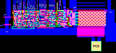
si6525_11_pc0.png [ 128.82 KiB | Viewed 1007 times ]

Attachment:
6525_11_pc0.png
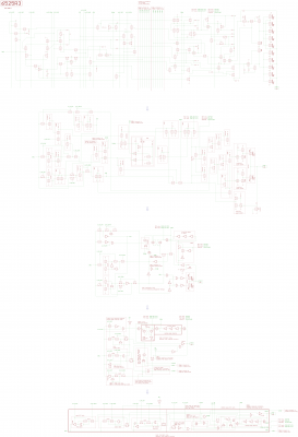
6525_11_pc0.png [ 383.03 KiB | Viewed 1007 times ]


Top
 Profile  
Reply with quote  
Display posts from previous:  Sort by  
Post new topic Reply to topic  [ 30 posts ]  Go to page 1, 2  Next

All times are UTC


Who is online

Users browsing this forum: Google [Bot], handyandy and 27 guests


You cannot post new topics in this forum
You cannot reply to topics in this forum
You cannot edit your posts in this forum
You cannot delete your posts in this forum
You cannot post attachments in this forum

Search for:
Jump to: