Well, curiosity finally got the better of me and I went and breadboarded up one of my "Rockwell R65C02P4" parts to see if it worked, at least in a basic way.
I used a 4 MHz crystal oscillator, both directly into the Φ0 input of the MPU and divided down via a 74LS161 to get 2 MHz and 1 MHz clocks, so I could test at all three of those clock frequencies. I did the usual thing with pull-ups and pull-downs to have a running system with NOP ($EA) on the data bus.
The good news is that it seems to do the right thing (address bus incrementing every two clock cycles) at 1 MHz, 2 MHz and even 4 MHz. So it's some sort of 6502, at least, and doesn't totally fail at the rated speed.
But the bad news is that it draws around 100 mA (the same at all three frequencies), which points to it being an NMOS part, right? And I'm also thinking that maybe it's not really a 4 MHz part: at 1 MHz my Φ2 output looks pretty squarish (better than some I've seen), but at 4 MHz the rising edge is more a casual, "I'll get there eventually" curve that takes most of its half of the cycle to get near the peak. Now I am a total noob when it comes to real-world clock signals, but this doesn't look so good to me.
Attachment:
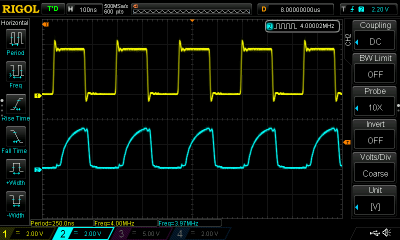 R65C02_4Mhz_phi0_phi2.png [ 51.95 KiB | Viewed 1343 times ]
Anyway, now that I've started in on this, I'm thinking I may just cons up a little SBC with ZIF sockets and jumpers that would let me more easily test this stuff, both with hardwired NOP (ideally set with a DIP switch so I can test different NOPs) and test programs in an EEPROM. Plus I guess I could use it for development or something.


