6502.org Forum  Projects  Code  Documents  Tools  Forum
It is currently Thu May 02, 2024 11:54 am

All times are UTC


Post new topic Reply to topic  [ 7 posts ] 
Author Message
 Post subject: My 65C02 based computer
PostPosted: Sat Dec 07, 2019 4:22 pm 
Offline

Joined: Wed Oct 16, 2019 11:17 pm
Posts: 34
Hello,

I saw Ben Eater's video on the 65C02 and got hooked. I set out to build my own computer, and this is what I've come up with. I haven't programmed it to do much yet, but I do have plans for it.

Attachment:
Everything.jpg
Everything.jpg [ 29.86 KiB | Viewed 678 times ]


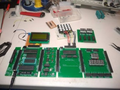
As you can see, it's a modular computer, allowing you to build it out, tear it down and build it up differently.

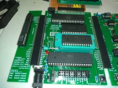
I'll start with the main board.

Attachment:
Main_add.jpg
Main_add.jpg [ 34.06 KiB | Viewed 678 times ]


From the bottom, working up, is the 65C02, an AT28C256 ROM, an AS6C2256SA RAM, and a 65C22. The 65C22 is rotated 180 degrees so pin 1 is on the right to get PA and PB facing the top of the board.

On the left is my addressing logic. It uses standard 74 series logic gates to put the RAM at $0000-$3FFF, the ROM at $8000-$FFFF and the VIA at $6000-$600F (really goes to $6FFF). By having the addressing board separate, I can keep the main board setup, and swap out the small addressing board to reconfigure the computer quickly.

Just to the left of the ROM is a spot for an oscillator. It's not populated right now because I'm using a clock based on Ben Eater's clock design.

Attachment:
Clock.jpg
Clock.jpg [ 34.59 KiB | Viewed 678 times ]


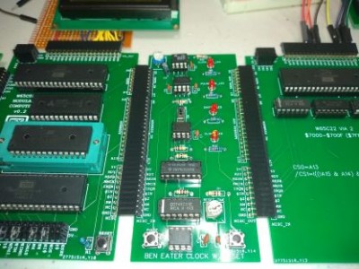
The clock board creates a clock signal with the 555 timer on the top of the board. The next 555 timer down creates a single shot pulse using the Pulse button in the lower left. There is a switch and a 555 timer below that which allows me to select between the clock signal and the pulse signal by using the 74157 data selector below it. Finally, there is a reset circuit at the bottom of the board that holds the reset line low for a little bit when the board powers up.

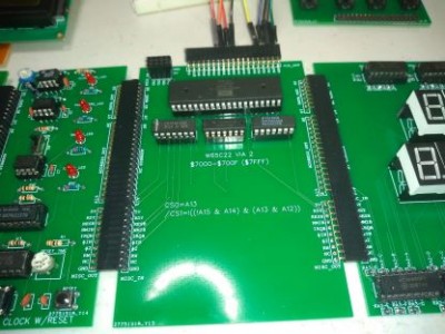
To the right of that is the second VIA on my computer:

Attachment:
VIA_2.jpg
VIA_2.jpg [ 31.27 KiB | Viewed 678 times ]


It's just a 65C22 turned around with basic logic chips below it to address it at $7000-$700F ($7FFF). Note that there are gates available on the logic chips on the addressing board shown earlier, and if the computer weren't modular, I could have used them instead of a new set of chips. But that's the price you pay for the modular design.

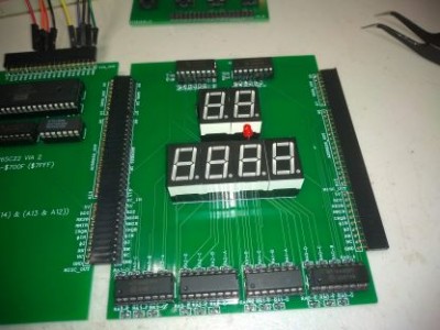
Next over is an address and data display board:

Attachment:
add_data.jpg
add_data.jpg [ 27.99 KiB | Viewed 678 times ]


This uses MC14495P seven segment display drivers to display what is currently on the address and data lines. When I slow down the clock, or use the Pulse feature to go through a running program step by step, this helps with troubleshooting.

The MC14495Ps aren't made anymore. It was difficult finding a chip that could display the hex values, but once I settled on a chip, they were there on eBay. I could have gone for a microprocessor design, but I wanted to stick to the 8-bit theme, and felt that a microprocessor chip would detract from the overall feel of the computer. I may change that at some time, as one of the 10 MC14495Ps barely works.

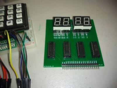
Above that is the VIA data board.

Attachment:
VIA_data.jpg
VIA_data.jpg [ 22.65 KiB | Viewed 678 times ]


This can be plugged into the header above either VIA to display what is on PA and PB. It also uses the MC14495P decodes to display the hex values.This was very helpful in getting the LCD running.

Speaking of the LCD, as you can see in the first picture, it's a board I threw together myself from perfboard, but it fits right into the header of the VIA. I do have a board designed that includes a VIA and an LCD in it, but haven't ordered it yet. I'm not really sure I'm going to

And finally, you see a keypad wired up to the second VIA using a breadboard. I'm still working on the code to make the keypad work, so I don't have it soldered up to anything (well, I did--you can see the board next to it, but it didn't work).

All of my designs are available on EasyEDA:

Main Board
Address board
Clock
VIA
Address/data board
VIA data

The one thing that is missing from this is the ACIA chip. You can almost see them to the right in the first picture. They are just sticking out. I'm waiting on crystals to start playing with them. Once I get them running, I'll put one on a board with a VIA and some address decoding. I'll put a USB port on the bottom, and some supporting hardware to communicate with it via USB on my laptop. But that's a little way's away.

Thanks for looking!


Last edited by rickseiden on Sat Dec 07, 2019 9:28 pm, edited 1 time in total.

Top
 Profile  
Reply with quote  
PostPosted: Sat Dec 07, 2019 4:34 pm 
Offline
User avatar

Joined: Sun Oct 18, 2015 11:02 pm
Posts: 428
Location: Toronto, ON
Nice job! I especially like the modular design — lots of potential for different configurations and experiments. Cool. Thanks for posting the pics. The boards looks great.

_________________
C74-6502 Website: https://c74project.com


Top
 Profile  
Reply with quote  
PostPosted: Sat Dec 07, 2019 4:53 pm 
Offline
User avatar

Joined: Thu Dec 11, 2008 1:28 pm
Posts: 10793
Location: England
Very nice! And welcome. And good work with the hex-valued seven-segment display!


Top
 Profile  
Reply with quote  
PostPosted: Sat Dec 07, 2019 10:56 pm 
Offline
User avatar

Joined: Fri Dec 12, 2008 10:40 pm
Posts: 1000
Location: Canada
Very cool! I like it. I also like your hex displays.

Attachment:
HexDisp_1.jpg
HexDisp_1.jpg [ 132.19 KiB | Viewed 640 times ]

Great minds think alike.

I too used the MC14495P. I have drawer full of them. I also included an 74ACT574 so I can use it with faster machines.

However, there is the Maxim ICM7218/7228 that I believe is still being manufactured. It has a parallel interface and can drive up to 8 digits. The default decoding mode is hex, however it has a no-decode mode for direct segment manipulation and a user defined decode mode, well for whatever you want. I actually have a couple of these I recently discovered in a unsorted parts box. I do plan to make a demo/experimental board with one of these on it to hoots and giggles - just have to find the time ...

_________________
Bill


Top
 Profile  
Reply with quote  
PostPosted: Sun Dec 08, 2019 2:27 pm 
Offline

Joined: Wed Oct 16, 2019 11:17 pm
Posts: 34
Thanks everyone for the kind words.

Interesting comment about about the ICM7218/7228. I'll look into those. Thanks.


Top
 Profile  
Reply with quote  
PostPosted: Mon Dec 09, 2019 4:14 am 
Offline
User avatar

Joined: Sat Dec 01, 2018 1:53 pm
Posts: 727
Location: Tokyo, Japan
I too really like this modular idea, particularly having a separate address decoding and clock boards!

rickseiden wrote:
To the right of that is the second VIA on my computer....
It's just a 65C22 turned around with basic logic chips below it to address it at $7000-$700F ($7FFF). Note that there are gates available on the logic chips on the addressing board shown earlier, and if the computer weren't modular, I could have used them instead of a new set of chips. But that's the price you pay for the modular design.

Actually, it doesn't need to be. One solution is to add additional select lines to your bus, the way the Commodore 64 did with its expansion/cartridge port. Though the cartridges could do their own decoding if they really wanted to, normally they'd just use the /ROML (low ROM, $8000-$9FFF), /ROMH (high ROM, $A000-$BFFFF or $E000-$FFFF, depending), /IO1 ($DE00-$DEFF) or /IO2 ($DF00-$DFFF) signals to enable whatever ROM or I/O they had in the cartridge.

Then you can just add jumpers to each expansion board to wire up the correct select lines and boom, as much or as little I/O as you want, whatever you want it.

I'm also curious, why did you decide to go with pin headers on each side instead of a backplane system? Just for ease of asssembly and general mucking about?

_________________
Curt J. Sampson - github.com/0cjs


Top
 Profile  
Reply with quote  
PostPosted: Mon Dec 09, 2019 11:23 am 
Offline

Joined: Wed Oct 16, 2019 11:17 pm
Posts: 34
cjs wrote:
I too really like this modular idea, particularly having a separate address decoding and clock boards!

rickseiden wrote:
To the right of that is the second VIA on my computer....
It's just a 65C22 turned around with basic logic chips below it to address it at $7000-$700F ($7FFF). Note that there are gates available on the logic chips on the addressing board shown earlier, and if the computer weren't modular, I could have used them instead of a new set of chips. But that's the price you pay for the modular design.

Actually, it doesn't need to be. One solution is to add additional select lines to your bus, the way the Commodore 64 did with its expansion/cartridge port. Though the cartridges could do their own decoding if they really wanted to, normally they'd just use the /ROML (low ROM, $8000-$9FFF), /ROMH (high ROM, $A000-$BFFFF or $E000-$FFFF, depending), /IO1 ($DE00-$DEFF) or /IO2 ($DF00-$DFFF) signals to enable whatever ROM or I/O they had in the cartridge.

Then you can just add jumpers to each expansion board to wire up the correct select lines and boom, as much or as little I/O as you want, whatever you want it.


If I do a redesign on the boards, I'll have to give that a try.

cjs wrote:
I'm also curious, why did you decide to go with pin headers on each side instead of a backplane system? Just for ease of asssembly and general mucking about?


I went with the pins for two reasons. First, I didn't know what a backplane system was until you mentioned it and I looked it up. Second, because I wanted everything laid out next to each other while I kept it modular so it was easier to muck about. You could convert this design to more of a backplane system by creating a backplane board, and then turning the existing boards on their sides to plug them in.


Top
 Profile  
Reply with quote  
Display posts from previous:  Sort by  
Post new topic Reply to topic  [ 7 posts ] 

All times are UTC


Who is online

Users browsing this forum: Google [Bot], viridi and 9 guests


You cannot post new topics in this forum
You cannot reply to topics in this forum
You cannot edit your posts in this forum
You cannot delete your posts in this forum
You cannot post attachments in this forum

Search for:
Jump to: