6502.org Forum  Projects  Code  Documents  Tools  Forum
It is currently Sat Apr 27, 2024 5:07 pm

All times are UTC


Post new topic Reply to topic  [ 189 posts ]  Go to page Previous  1 ... 9, 10, 11, 12, 13  Next
Author Message
PostPosted: Sun May 07, 2023 6:53 am 
Offline
User avatar

Joined: Thu Dec 11, 2008 1:28 pm
Posts: 10793
Location: England
Well done! It's nice when things get simpler as they get closer to correctness (not sure though if that's what happened in this case.)


Top
 Profile  
Reply with quote  
PostPosted: Fri Jun 23, 2023 4:43 pm 
Offline

Joined: Fri Jan 25, 2019 2:29 pm
Posts: 191
Location: Madrid, Spain
Hi everyone!

Today, I have released a new version of the 74HCT6526. v0.2.2 is out, and it brings a lot of fixes.

I've finally managed to run TEST 02 successfully, both in NEW and OLD modes.

Attachment:
20230622_test02_old_ok.jpg
20230622_test02_old_ok.jpg [ 3.27 MiB | Viewed 3803 times ]

Attachment:
20230622_test02_new_ok.jpg
20230622_test02_new_ok.jpg [ 3.71 MiB | Viewed 3803 times ]


This test starts a TIMER cycle at $0100. During the countdown, it samples ICR twice, and outputs the contents to screen (Each column in the test represents a cycle). With the Commodore PETSCII character map, @ = 0, A = 1 and B = 2. Also, if bit7 is set , the character will be inverted.

The left side tests are for TIMERA, right side for TIMERB. Also, in the two upper tests IRQ are disabled, and enabled on the lower. Within the interrupt handler, ICR and TIMER are sampled and outputted into the screen.

Each cycle, the timer count is reduced by one, so over the 16 cycles, any possible quircks of the ICR will manifests themselves. It took some butchering though...

Attachment:
20230622_test02_b3@v0.2.2.jpg
20230622_test02_b3@v0.2.2.jpg [ 5.12 MiB | Viewed 3803 times ]


But I got it working. The three switches on the board, control the three differences between OLD and NEW modes, so for it to be correct, all the switches need to be in the same position.

Let's dive a bit into the details. I'll start with NEW mode, as it seams more reasonable.
  • Whenever a interrupt source fires (TIMERS, SDR, TOD or FLAG input) the corresponding ICR bit is set inmediately. I did this by feeding the interrupt source directly into the set pin of its DFF
  • If the corresponding bit in MASK register is set. ICR7 is also set at the same time.
  • Whenever ICR7 is set, /IRQ goes low
  • Whenever ICR is read the /OE signal for the register is fed into a chain of two DFF clocked by /PHI2. They generate two delayed signals, /ICRCLR1 delayed by 1 cycle, and /ICRCLR2, by two cycles
  • All ICR bits are cleared by /ICRCLR1

However, in OLD mode, it feels like someone didn't sleep properly that day, when drawing the masks for the ICs!
  • ICR bit are set the same as in NEW mode.
  • But, this time, ICR7 is delayed by one cycle. In my design, the NEWICR7 is fed into a second DFF which we can call OLDICR7. Even though OLDICR7 is delayed one cycle, it still clears by /ICRCLR1
  • Again, /IRQ follows ICR7. So it's also delayed by one cycle in OLD mode
  • TimerB is where the fun is. ICR1 is cleared by /ICRCLR2.

This set of one cycle delays are what cause the famous timerb bug, at least, on my design. Of course the original 74HCT6526 didn't use DFF, but relied on latches, so of course, the circuit won't match. At one point I had all ICR bits cleared by /ICRCLR2, and all interrupt sources manifest the bug.

As a bonus, in this new release, TOD has finally been added. I haven't ordered the boards yet, but the family is now complete. Also, a second unit is being built. I'm now 100% sure, that by the end of 2023, I will have a C64 running with two 74HCT6526 and, mostly, bug free.

There's still some soldering and debugging to do, but... as I said so many times before...

daniMolina wrote:
PD. So close... I am so close!


Cheers!


Top
 Profile  
Reply with quote  
PostPosted: Fri Jun 23, 2023 6:58 pm 
Offline

Joined: Mon Jan 19, 2004 12:49 pm
Posts: 660
Location: Potsdam, DE
Polite round of applause; beer held in readiness!

Neil


Top
 Profile  
Reply with quote  
PostPosted: Sat Jun 24, 2023 6:29 am 
Offline

Joined: Tue Jul 05, 2005 7:08 pm
Posts: 990
Location: near Heidelberg, Germany
Excellent work!

_________________
Author of the GeckOS multitasking operating system, the usb65 stack, designer of the Micro-PET and many more 6502 content: http://6502.org/users/andre/


Top
 Profile  
Reply with quote  
PostPosted: Mon Oct 16, 2023 7:10 pm 
Offline

Joined: Fri Jan 25, 2019 2:29 pm
Posts: 191
Location: Madrid, Spain
Hi everyone!

This is my "return to work after summer season" post. It did however take a bit longer than I expected... as usual.

I took a very long detour through another complete unrelated project (I can now solder QFN!) so the 74HCT6526 had to wait a bit.

Not a lot of real progress though. The design has not changed since June, and there's no new version in the making, but the family has grown :

Attachment:
20231016_205748.jpg
20231016_205748.jpg [ 995.83 KiB | Viewed 3646 times ]


A second unit is now built, at least up to where my IC stash allowed me. A new order has been place for TOD pcbs, and all remaining ICs. When they get here, is when the real fun will begin :)

Cheers!


Top
 Profile  
Reply with quote  
PostPosted: Tue Nov 07, 2023 9:21 pm 
Offline

Joined: Fri Jan 25, 2019 2:29 pm
Posts: 191
Location: Madrid, Spain
Hi again.

Slowly, but still moving on.

After receiving more PCBs and parts, I now have two perfectly working 74HCT6526s (Except for TOD, that's still in the making)

Attachment:
20231107_212823.jpg
20231107_212823.jpg [ 2.22 MiB | Viewed 2480 times ]


Attachment:
20231107_213253.jpg
20231107_213253.jpg [ 3.21 MiB | Viewed 2480 times ]


From left to right, B0 (Ports and DDR), B1 (Timer + CREG A), B2 (Timer + CREG B) and B3 ( SDR + ICR)

First unit built is at the bottom, new unit at the top. All boards are upgraded to the most recent version and, you can tell I'm improved my skiils for patching... There are still things I don't like but, as someone said some time ago....

Younger version of myself wrote:
first, make it work, then make it fast, then make it beautiful.


Getting there.... :)

Cheers!


Top
 Profile  
Reply with quote  
PostPosted: Tue Nov 07, 2023 9:30 pm 
Offline

Joined: Tue Jul 05, 2005 7:08 pm
Posts: 990
Location: near Heidelberg, Germany
Cool, great work! Thanks for the update!

_________________
Author of the GeckOS multitasking operating system, the usb65 stack, designer of the Micro-PET and many more 6502 content: http://6502.org/users/andre/


Top
 Profile  
Reply with quote  
PostPosted: Thu Nov 09, 2023 5:44 pm 
Offline

Joined: Fri Jan 25, 2019 2:29 pm
Posts: 191
Location: Madrid, Spain
Attachment:
20231109_181500.jpg
20231109_181500.jpg [ 2.1 MiB | Viewed 2419 times ]


Look who's keeping track of the Time Of Day!

Yay!

Of course, not everything works. Even though I was showing off my soldering skills on my previous post, I'm pretty sure most of my issues now are build-quality related. I've been having ton of issues with my interPCB connectors from the very beggining, as they never seem to make proper contact... 5 boards, with 60 connections per board, that's a grand total of 300 hundred and, pretty much a single one failing, causes weird and impredictable issues.

But, anyway, TOD is ticking. I can't write to it, I can't stop it, I can only read it. But at least, the 7 chained 74hc193 can keep track of time. That's something.

Time for debugging!

Ninjaedit: After reshuffling the boards a bit... I can now write to TOD, so yeah, TOD board is going to need a good reflow of everything, just to be on the dafe side..


Top
 Profile  
Reply with quote  
PostPosted: Thu Nov 09, 2023 6:12 pm 
Offline

Joined: Mon Jan 19, 2004 12:49 pm
Posts: 660
Location: Potsdam, DE
At the risk of being a pain in the ass, does the circuit simplify with hc190 or 191 instead of 193? i.e. decade counters instead of binary?

Neil


Top
 Profile  
Reply with quote  
PostPosted: Thu Nov 09, 2023 7:10 pm 
Offline

Joined: Fri Jan 25, 2019 2:29 pm
Posts: 191
Location: Madrid, Spain
barnacle wrote:
At the risk of being a pain in the ass


For me, no idea will ever be a pain in the ass. I wouldn't had reached where I am, if it wasn't for all the help received here, so don't worry about that. :D


barnacle wrote:
Does the circuit simplify with hc190 or 191 instead of 193? i.e. decade counters instead of binary?

Neil


Indeed, it would be simpler, although not by much. I think it could save 4 or 5 gates, so it's not a huge difference. I considered it, but HC190s are priced much higher than HC193s, and there are 13 of them on each 74HCT6526. So cost was a big factor in the decision.

Also, some interesting facts about the TOD on a real 6526. Even though it acts as a (somewhat) BCD counter, the counters (some of them) are actually full 4 bit counters. If you write 1A in the seconds register, it will go 1B>1C>1D>1E>1F>10>11...>19 and then, and only then, it will flip to 20. So, only when the counter hits A (10) it resets to 0 and 'ticks' the next counter. You can find more details on this old post.

I haven't fully replicated this. I generate a 'tick' whenever bits 3 and 1 are high, So 1010 ticks, but 1011 will also, and 1110 or 1111 will too. This way, only a 2AND gate is enough to generate the tick. Otherwise, 2 inverters plus a 4AND gate are needed to 100% replicate each digit.

I even considered using some GALs, or some small CPLD. I've only taken a little peek at this, and I think a ATF1504 could handle the whole TOD. But that would be cheating :)

Cheers!


Top
 Profile  
Reply with quote  
PostPosted: Thu Nov 09, 2023 9:37 pm 
Offline

Joined: Fri Jan 25, 2019 2:29 pm
Posts: 191
Location: Madrid, Spain
Ok, last post for today... and yes... I'm going to show off a bit :)

If you take a peek into the TOD schematic you can see everything is quite simple.

  • Some registers to store ALARM value
  • A bunch of counters, with some (simple) logic to reset when they reach 6 or 10
  • Some comparators to detect the ALARM condition
  • A handful of ANDs/ORs to select everything from above

But, when you reach page 11 of the schematic... that's where all the fun is:

Attachment:
B4.sch.v0.2.2.page11.png
B4.sch.v0.2.2.page11.png [ 657.03 KiB | Viewed 2382 times ]


A single counter for the hours units, a DFF for the hours tens, another for the PM/AM Flag.

What a mess! the counter, together with the first DFF has to do this cycle :

00 > 01 > 02 > 03 > 04 > 05 > 06 > 07 > 08 > 09 > 10 > 11 > 12

Units counter resets at 10, or 3, depending on the TENS value. This took me a while.

I can tick TOD from two different sources. The onboard Arduino can generate a 60Hz signal, idea to keep track of real time, but I can disable that and use the 6522 on my SBC to tick TOD, as fast as I can.

I've been running in a tight loop, fast forwarding time, for 30 minutes already. Enough to to at least 5 full 24 hour cycles. And I'm comparing my 74HCT6526 with a real MOS6526... and they are completely in sync, down to the tenths of second.

Only issue... AM/PM flag does not flip. Will get there :)

Cheers!


Top
 Profile  
Reply with quote  
PostPosted: Mon Nov 13, 2023 3:18 pm 
Offline

Joined: Fri Jan 25, 2019 2:29 pm
Posts: 191
Location: Madrid, Spain
Here we go!

Please meet the last member to join the family:

Attachment:
TOD_B4.jpeg
TOD_B4.jpeg [ 178.52 KiB | Viewed 2299 times ]


TOD is done and, after my initial tests, it mostly works, with only a couple of issues that can be easily be fixed :)

This is the full stack.

Attachment:
FS1.jpeg
FS1.jpeg [ 177.01 KiB | Viewed 2299 times ]

Attachment:
FS2.jpeg
FS2.jpeg [ 176.59 KiB | Viewed 2299 times ]


That is all. The 74HCT6526 is now complete. Yes, still buggy, but complete. Let's see what our issues are.

- On powerup (or reset) TOD should not be counting, but it is. A write to the tenths register starts the count, a write to the hours register stops the count. On my design, TOD is and-gated with a signal I've called COUNT.

Attachment:
count_issue.png
count_issue.png [ 14.18 KiB | Viewed 2299 times ]


The idea was... when /RES goes high, that became a clock pulse for the flipflop that generates COUNT. With its Data pin tied to GND... on reset, COUNT should be 0. Right? Nope. Wrong. As I'm forcing a write to all registers on reset, /LOADT and /LOADH are active, so both /SET and /RESET inputs to the DFF are asserted simultaneously. When the /RES, /LOADT and /LOADH finally goes high, COUNT is always 1.
This will be fixed by taking /Q as COUNT, and swaping /LOADT and /LOADH on the flipflop.

- AM/PM flag does not flip.

Attachment:
AM_PM_FLIP_issue.png
AM_PM_FLIP_issue.png [ 9.93 KiB | Viewed 2299 times ]


AM/PM flag flips whenever 12 is on the hours register. It doesn't matter if the 11th hour became the 12th, or if a 12 was written there. Both makes AM/PM flag to switch.

What am I doing here? U428B generates the H7_FLIP signal. This is fed into U427B clock pin. U427B Data input is fed from its /Q output so, whenever H7_FLIP goes high, AM/PM flips. The output rom U429 goes low whenever 12 is on the Hours register (Its input comes from an AND gate fed from the HOURS register). The idea is, whenever we see a 12, H7_FLIP goes high, because this signal is tied to the...mmmm...../RESET??? Big mistake! It should be tied to /SET, with /RESET being connected to VCC. Should be an easy fix too!

- Last issue... I'm getting no interrupts out of TOD. 4 chained 74HC688 compare the value in the TOD registers with the value in the ALARM registers.

Attachment:
comparator.png
comparator.png [ 52.47 KiB | Viewed 2299 times ]


I don't see how could this fail, so probably, a bad solder somewhere.


Apart from all this, I'm having some issue with the SDR. It seems to properly receive bytes from another CIA, but fails to send them. This has worked before, so it's, again, probably a bad solder. Some inspection and debugging should take care of it.

Fixing this issues, will render the 74HCT6526 complete and pretty much cycle exact. There are some test left to be run from the Vice emulator test suite to check how accurate the build is. I know SDR and TOD IRQs are not exact, but that is probably OK for 99.99% of the C64 software out there, and I also know that TOD invalid counts are not right. I have a new design in progress, using 74HC84 4 bit comparators that could probably work. But again... not critical.


Top
 Profile  
Reply with quote  
PostPosted: Tue Nov 14, 2023 6:16 am 
Offline
User avatar

Joined: Mon Aug 30, 2021 11:52 am
Posts: 251
Location: South Africa
I don't really have anything valuable to add. Just thought I'd say I'm really enjoying watching the progress :D


Top
 Profile  
Reply with quote  
PostPosted: Fri Nov 17, 2023 10:31 pm 
Offline

Joined: Fri Jan 25, 2019 2:29 pm
Posts: 191
Location: Madrid, Spain
AndrewP wrote:
I don't really have anything valuable to add. Just thought I'd say I'm really enjoying watching the progress :D


As the end of the project is getting closer and closer now... I've been revisiting my goals from the very beginning, more than 5 years ago. Having other people enjoy the journey was never a goal but, it should have been!

I'm glad I can give something back to the community. It has been a beautiful experience!


daniMolina wrote:
- On powerup (or reset) TOD should not be counting, but it is. A write to the tenths register starts the count, a write to the hours register stops the count. On my design, TOD is and-gated with a signal I've called COUNT.

The idea was... when /RES goes high, that became a clock pulse for the flipflop that generates COUNT. With its Data pin tied to GND... on reset, COUNT should be 0. Right? Nope. Wrong. As I'm forcing a write to all registers on reset, /LOADT and /LOADH are active, so both /SET and /RESET inputs to the DFF are asserted simultaneously. When the /RES, /LOADT and /LOADH finally goes high, COUNT is always 1.
This will be fixed by taking /Q as COUNT, and swaping /LOADT and /LOADH on the flipflop.


The design was, after all, correct. The data input to the FF was floating so... Fix this, and COUNT is working now as expected.
daniMolina wrote:

- Last issue... I'm getting no interrupts out of TOD. 4 chained 74HC688 compare the value in the TOD registers with the value in the ALARM registers.

I don't see how could this fail, so probably, a bad solder somewhere.


A good reflow on all the comparators, and problem solved.

daniMolina wrote:
- AM/PM flag does not flip.

Attachment:
AM_PM_FLIP_issue.png


AM/PM flag flips whenever 12 is on the hours register. It doesn't matter if the 11th hour became the 12th, or if a 12 was written there. Both makes AM/PM flag to switch.

What am I doing here? U428B generates the H7_FLIP signal. This is fed into U427B clock pin. U427B Data input is fed from its /Q output so, whenever H7_FLIP goes high, AM/PM flips. The output rom U429 goes low whenever 12 is on the Hours register (Its input comes from an AND gate fed from the HOURS register). The idea is, whenever we see a 12, H7_FLIP goes high, because this signal is tied to the...mmmm...../RESET??? Big mistake! It should be tied to /SET, with /RESET being connected to VCC. Should be an easy fix too!


This is the only problem left. The only one. I've run out of time for today... but it can be done by Sunday.

Oh yes, something is also failing when sending bytes out of the SDR, but it has worked before. B3 is in pretty bad shape... I've done A LOT of rework on it, and I do not trust it. Maybe I will build a new one from scratch.

So close!!!!


Top
 Profile  
Reply with quote  
PostPosted: Sun Nov 19, 2023 7:59 pm 
Offline

Joined: Fri Jan 25, 2019 2:29 pm
Posts: 191
Location: Madrid, Spain
Hi all!

I've got it :D

The AM/PM fix was trickier than expected, but still doable.

This was my starting point

Attachment:
AM_PM_FLIP_issue.png
AM_PM_FLIP_issue.png [ 9.93 KiB | Viewed 2183 times ]


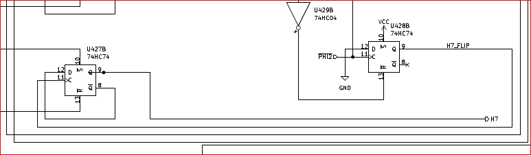
Let's recap. The FF on the left holds the AM/PM bit (TODH7). The input to the inverter U429B is a signal than goes high, whenever 12 is on TODH (Ignoring TODH7). The FF on the right should go high whenever TODH7 has to flip (at 12) but it was incorrectly wired. It never went high.

To fix this the data input has been rewired to VCC (So the FF is always high, until resetted by the 12 hour signal). Also the H7_FLIP signal was rewired and now comes from /Q. When we had 12 in TODH, H7_FLIP went high and flipped the AM/PM bit. Success!!!!

Nope. Not yet.

What I said above is indeed true, but there's another scenario that flips AM/PM. When a 12 is written into TODH, the flag flips, so 92 ends up there. When 92 is written, same thing happens, and 12 is there.

The /SET and /RESET inputs of U427B go low when a 1 is written to TODH7, or a 0, respectively. When a 12 or 92 are written to the TODH, the H7_FLIP signal goes high, but the /SET or /RESET prevail so the flip does not happen.

To fix this, I had to insert another FF to delay H7_FLIP by one cycle. And now, when I write 12 I get 92, and when I write 92, I get 12. Success!!

Nope, almost there, but still...

Let's suppose I write 12 to TODH. 12 get stored in the register. H7_FLIP goes high (As its FF /RESET goes low). Then it gets delayed by one cycle, and flips TODH7, resulting in the expected 92.

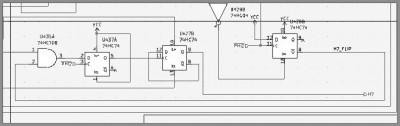
What happenes if I write 12 again? I get 12, because, the H7_FLIP FF never comes out of reset. So... I ANDed H7_FLIP with the /LOADH signal (The write register signal). So, if H7_FLIP is high, and we write another 12... H7_FLIP, flips again.
Success??

Yes. Now my TOD reflects the real TOD behaviour.

Attachment:
ampm_fix.jpg
ampm_fix.jpg [ 33.19 KiB | Viewed 2183 times ]


And with this, all the unit tests I've got work. Keep in mind these tests don't go too deep, so this only means it more or less work, but it doesn't mean I'm cycle exact. So, what are the next steps?

- Find out what's going on with SDR. Still not sending, and so far, I'm clueless. It did work before so it shouldn't be too difficult to find out what's wrong, but it's resisting.
- Build the second TOD, to complete the second 74HCT6526
- Remove and socket second CIA on my C64
- Complete all VICE Tests. These do go deep. In fact, passing all tests, pretty much guaranteed a complete and cycle exact 6526.
- Plug both 74HCT6526s into the SBC6526... and crank up the clock! Let's see how far this thing goes.

Somewhere along the way, a v0.2.3 will be released will the latest changes. Also, I do not forget that my TOD does not replicate the invalid count cycles. And improved TOD should be done at some point too.

Ahh... Do you feel that? It's completeness, and I like it very much.


Top
 Profile  
Reply with quote  
Display posts from previous:  Sort by  
Post new topic Reply to topic  [ 189 posts ]  Go to page Previous  1 ... 9, 10, 11, 12, 13  Next

All times are UTC


Who is online

Users browsing this forum: No registered users and 37 guests


You cannot post new topics in this forum
You cannot reply to topics in this forum
You cannot edit your posts in this forum
You cannot delete your posts in this forum
You cannot post attachments in this forum

Search for:
Jump to: