6502.org Forum  Projects  Code  Documents  Tools  Forum
It is currently Mon Sep 23, 2024 8:27 pm

All times are UTC


Post new topic Reply to topic  [ 6 posts ] 
Author Message
PostPosted: Wed Feb 14, 2018 10:15 am 
Offline

Joined: Wed Jan 24, 2018 4:05 am
Posts: 14
Hello again everyone!

I have been building a computer on breadboard and have been having very good luck with it up until now. I recently attempted to increase the size of my project from 4 breadboard panels, to 8. At the same time, I attempted to simplify my mess of wiring by extending the entire data bus vertically across two sets of rails (doing the same for the clock line, r/w line, IO active-low line, etc.)
Well, much to my chagrin even my +5v VCC line (30W power supply) dropped down to +2v on the far side of the two breadboard rails. I can run power lines directly to each breadboard panel, but there was no hope for my data bus! And oh the poor clock line!
I am trying to run at 2MHz, but I don't think I can even get 500kHz out of such a big breadboard arrangement. Perhaps I am ready to graduate to the next level.
How do you guys recommend I proceed? I am thinking I should move to protoboard and solder? And can I also ask, what about the I/O expandability? I am using the address decoding style from Garth's primer, so I have 10 I/O lines available to me. I am already using 4 of them and will most likely want to use all 10 I/O lines. Can I connect that many chips directly to the data pins of the CPU? 12 wires total coming off of each CPU data pin....?
Since that sounds kind of ridiculous to me, I thought maybe for so many chips I should be using expansion boards? But then I will have to buffer the bus, or stick a VIA in-between is that correct? I'm still trying to keep things simple where I can.
What do you recommend as the best approach for a "large" computer, if top speed is not crucial? (Keeping in mind I am still a beginner?)

Thanks as always for your time!


Top
 Profile  
Reply with quote  
PostPosted: Wed Feb 14, 2018 11:55 am 
Offline

Joined: Mon Aug 05, 2013 10:43 pm
Posts: 258
Location: Southampton, UK
After struggling with this exact same problem for a long time, I opted to move the core of the computer (glue logic, CPU, RAM, ROM, UART) onto a PCB with an expansion header onto breadboards which had the "secondary IO". I used IDC40 cable to link the two halves, since I had a load of headers and sockets.

Attachment:
IMAG0847.jpg
IMAG0847.jpg [ 268.14 KiB | Viewed 3344 times ]


That photo also shows some other breadboard bodgery I'm rather proud of, including a Shrink DIP adapter.

FWIW I'm convinced you absolutely can run reliable 2MHz (and more) computers spread over dozens of breadboards. It just requires:

:arrow: Very good quality breadboards
:arrow: Decent single core wires
:arrow: Patience to make a very tidy layout

I never really had all three, especially lacking was the last one. Hence I went for the PCB+IO on BB approach.

EDIT: Regarding buffers, I never bothered. I should have but since it worked without them...

_________________
8 bit fun and games: https://www.aslak.net/


Top
 Profile  
Reply with quote  
PostPosted: Wed Feb 14, 2018 12:49 pm 
Offline
User avatar

Joined: Fri Nov 09, 2012 5:54 pm
Posts: 1429
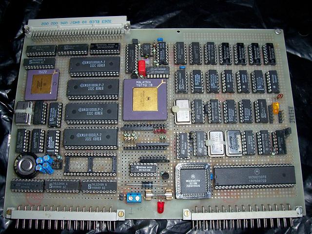
First, take a look at Oneironaut's Vulcan 74.

;---

When soldering a proto PCB:

Would suggest to use bare wire for GND and VCC.
Make sure that there are enough capacitors between GND and VCC, it's possible to solder them below the chip sockets.

And when wiring the address bus and data bus, sticking to the resistor color code simplifies debugging later.
Like: A0 -> black, A1 -> brown, A2 -> red, A3 -> yellow (had no orange wire on stock), A4 -> black again.

BTW: when using flat cables, try to make every second wire GND (like with old floppy and hard disk cables).

It's good to spend some thoughts first on how to arrange the chips on a PCB first before you start building.

Maybe it would be helpful to glue a piece of paper on top of the bigger chips describing the chip pinout.


Many years ago I had soldered my own 68020 computer: 32 Bit data bus, and at 29MHz that computer stopped to work reliable.

Image

Image


Top
 Profile  
Reply with quote  
PostPosted: Wed Feb 14, 2018 7:50 pm 
Offline
User avatar

Joined: Fri Aug 30, 2002 1:09 am
Posts: 8513
Location: Southern California
I think all the answers are in the 6502 primer, but I know everything won't sink in the first time through; so do re-read it. Of special relevance to the things you mention are sections 5 (specifically the part about bus transceivers, and no, you don't need them if all loads are CMOS and your clock speed is so low), 9, 10, and 12, and maybe 6. Then it might not be a bad idea to read more or less from beginning to end again, because the sections are organized in a logical way, meaning that just skipping around may result in missing important steps in the development.

_________________
http://WilsonMinesCo.com/ lots of 6502 resources
The "second front page" is http://wilsonminesco.com/links.html .
What's an additional VIA among friends, anyhow?


Top
 Profile  
Reply with quote  
PostPosted: Thu Feb 15, 2018 1:56 am 
Offline

Joined: Wed Jan 24, 2018 4:05 am
Posts: 14
Thanks for the links and comments everyone. It's appropriate that I should read the primer again, because in a lot of ways I feel like I'm starting over again!


Top
 Profile  
Reply with quote  
PostPosted: Sat Feb 17, 2018 11:55 pm 
Offline

Joined: Wed Nov 18, 2015 8:36 am
Posts: 102
Location: UK
My homebrew is spread on 8 breadboards - 4 large and 4 small, but mostly fills the interior space of a BBC Microcomputer case. The CPU runs at 2.68MHz, but I am using a ~21.7MHz base clock and dividing down for the video chip (~10.8MHz), with everything (2 x VIA, ACIA) running off the same clock as the CPU.

I've had problems over the time I have used breadboards, but agree with Aslak3's advice on quality parts, wire and tidy layout. Oneironaut's project is an amazing example of just how much can be done on breadboards.

My project isn't even that neat - most of the problems I have had came down to bad connections, poor power supply and poor breadboards (I replaced one very early on). But touch wood, despite the odd spurious issues, the computer has sat on these breadboards for 3 years now, and is pretty reliable.

https://hackaday.io/project/5789-6502-homebrew-computer


Top
 Profile  
Reply with quote  
Display posts from previous:  Sort by  
Post new topic Reply to topic  [ 6 posts ] 

All times are UTC


Who is online

Users browsing this forum: No registered users and 7 guests


You cannot post new topics in this forum
You cannot reply to topics in this forum
You cannot edit your posts in this forum
You cannot delete your posts in this forum
You cannot post attachments in this forum

Search for:
Jump to: