6502.org Forum  Projects  Code  Documents  Tools  Forum
It is currently Sat Jun 15, 2024 10:47 pm

All times are UTC


Post new topic Reply to topic  [ 9 posts ] 
Author Message
PostPosted: Wed Nov 14, 2018 10:15 pm 
Offline

Joined: Sat Feb 10, 2018 10:13 pm
Posts: 10
I've been meaning to post here the details about the system I've been building, since I couldn't have done it without the resources I've found here. I'll warn you up front that there is nothing terribly exciting about the build starting with the name: Retro-65.

The core of the system is a 65C02. It has 32KB of RAM, 16KB of EEPROM, a 6551 ACIA, and a 6526 CIA. I use a ATF16v8 for address decode and some basic glue logic and a 555 for the reset timer. The whole thing is built using wire-wrap on an old prototyping board I've had lying around for ages, which conveniently has power planes on both sides.

The Retro-65 does not have its own video, sound, or keyboard. I'd really like to add those at some point, but it may be a while before I get there... so all the UI is handled through the serial port. Two things that might be a little unique are two breakout boards from Adafruit: a TTL serial to USB converter based on the CP1204, and a micro-SD breakout board with a voltage level shift chip built in. I'm currently working on core routines to try to access an SD card for storage, bit banging through the CIA.

In terms of software, I've gotten EhBASIC and FigForth working on the board.

The memory layout is designed to match the Symon emulator to make it easier to test out code for it:

$0000 - $7FFF : RAM
$8000 - $800F : CIA
$8800 - $8803 : ACIA
$C000 - $FFFF : ROM (I made a mistake in ordering the EEPROMs and got the 32KB version. For simplicity sake, I just tie its A14 line low and use it as a 16KB EEPROM. Oops.)

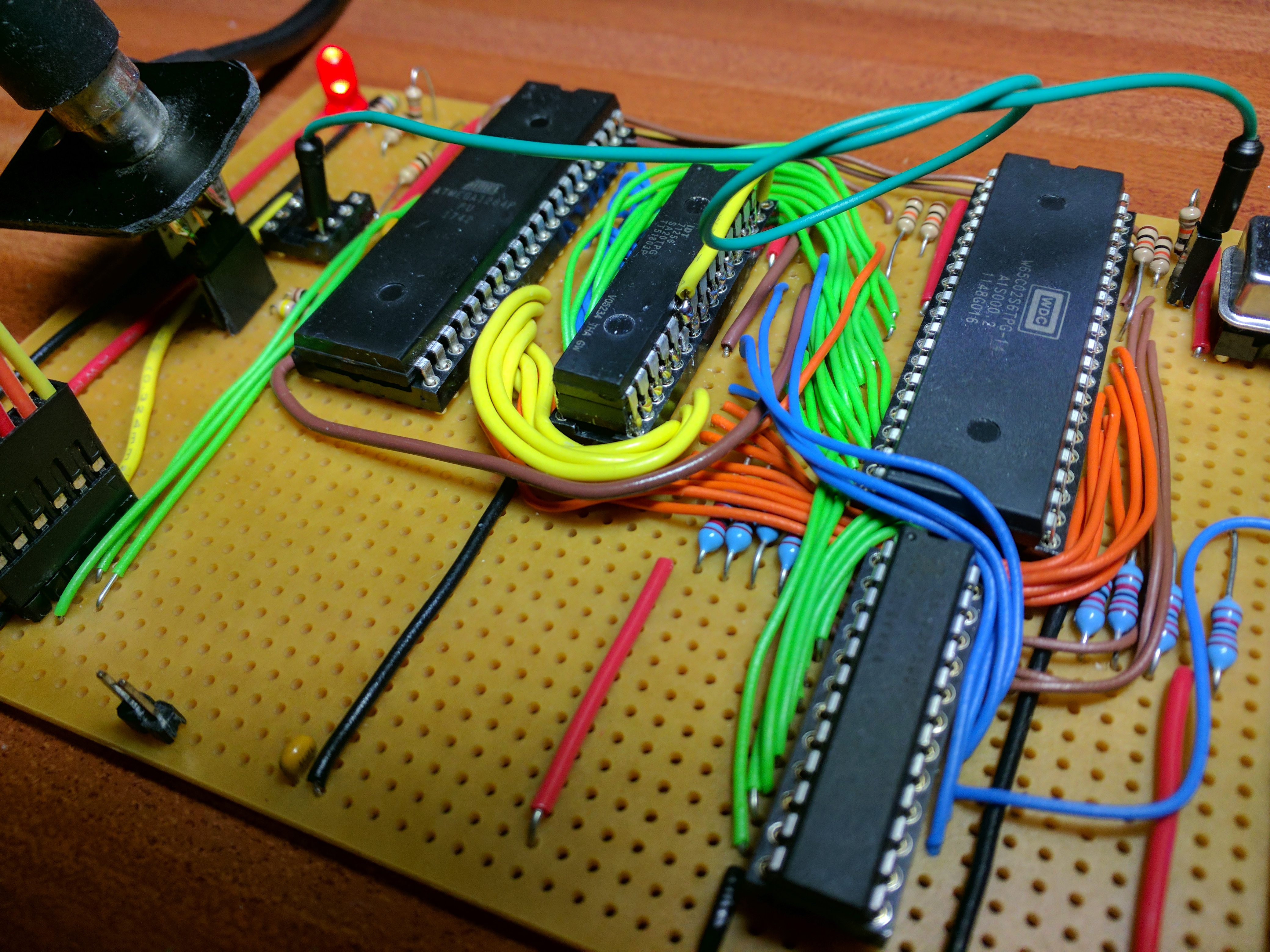
Here's a picture of the board:

Attachment:
Retro65_SDC.jpg
Retro65_SDC.jpg [ 1.95 MiB | Viewed 2592 times ]


And here are the schematics. The schematics don't show the caps, which I've put near all the main chips with the exception of the 6526. The 6526 was a late addition, and wanted to see if I could get away without a cap for it (well, really I didn't want to fiddle with wire wrapping another discrete component). The schematics may also have some errors by the way, since I had to redo them after something went wrong with my Kicad install.

Attachment:
Retro65_SDC.pdf [217.7 KiB]
Downloaded 122 times


I'll be very interested in any comments or suggestions for improvement.


Top
 Profile  
Reply with quote  
PostPosted: Wed Nov 14, 2018 10:46 pm 
Offline
User avatar

Joined: Thu Dec 11, 2008 1:28 pm
Posts: 10827
Location: England
Good to hear about your project!


Top
 Profile  
Reply with quote  
PostPosted: Wed Nov 14, 2018 11:00 pm 
Offline
User avatar

Joined: Tue Mar 05, 2013 4:31 am
Posts: 1378
Well, congrats on getting an initial system up and running... it's always rewarding to build up your first SBC and have it working! I've also been using a USB-Serial interface module for many years now, albeit I use FTDI products and implement RTS/CTS handshaking for the console port, which I also use for Xmodem downloads to the SBC. I've not yet dabbled with a SD-Card interface but some other folks out here have, IIRC.

As far as making suggestions go, that really depends on what your plans are. Overall, I would likely be more inclined to use a newer 65C22 over the 6526. Granted, the CIA has some other features and was used in the C64, but availability of these is less and will limit the upper clock speed of the overall board. Other bits to consider... RTC chip, additional serial and/or parallel ports. Really depends on what you want to do with the board next.

_________________
Regards, KM
https://github.com/floobydust


Top
 Profile  
Reply with quote  
PostPosted: Wed Nov 14, 2018 11:05 pm 
Offline
User avatar

Joined: Fri Dec 11, 2009 3:50 pm
Posts: 3366
Location: Ontario, Canada
Nice work, petrus! And I'm always glad to hear about Forth being used. Just be aware FIG Forth has some bugs, such as those listed here and elsewhere. And if you want maximum speed for SPI bit-banging (for the SD card) then these routines may interest you.

-- Jeff

_________________
In 1988 my 65C02 got six new registers and 44 new full-speed instructions!
https://laughtonelectronics.com/Arcana/ ... mmary.html


Top
 Profile  
Reply with quote  
PostPosted: Thu Nov 15, 2018 12:12 am 
Offline
User avatar

Joined: Thu May 28, 2009 9:46 pm
Posts: 8214
Location: Midwestern USA
Glad to see you've got it working. Looks good.

petrus wrote:
I've been meaning to post here the details about the system I've been building...I use a ATF16v8 for address decode and some basic glue logic...

What did you use to program the GAL?

Quote:
...and a 555 for the reset timer.

In your next design consider using a Maxim DS1813 reset generator in place of the 555 timer. Only one part, which is in a TO-92 package, and it responds to a push button grounding the reset line.

Also, a half-can oscillator in place of that full-can unit will save you some board real estate.

_________________
x86?  We ain't got no x86.  We don't NEED no stinking x86!


Top
 Profile  
Reply with quote  
PostPosted: Thu Nov 15, 2018 12:21 am 
Offline
User avatar

Joined: Fri Dec 11, 2009 3:50 pm
Posts: 3366
Location: Ontario, Canada
Petrus, in a post in another thread you mentioned modifying a 'C02 SBC to take an '816. Is it this board you're talking about?

Hacking for an '816 would be kinda extreme but doable. Adding a '245 transceiver and '573 address latch would be easy enough; I'd say the headache is adding RAM. IMO the best option (to save space and avoid lots of new wiring) is to use the third dimension and piggyback more than one memory IC in a single site.

Sticking with .3" wide DIP RAM's that'd be easy, despite being a little funny-looking if you use 3 chips stacked on top of the original RAM (for a total of 128K). Unfortunately, there are no high-capacity RAM's in .3" DIP packages; they're all .6" AFAIK. Even so, you could shuffle things slightly then arrange for the EEPROM and a .6" RAM to share a single site -- for example, solder a 512K by 8, 32-pin RAM chip (in a socket, perhaps) on top of the 28-pin EEPROM.

It's your call, of course, but if you opt to design a whole new board then these challenges would be avoided. And maybe you'd like to use a 6522 VIA instead of that CIA.

J :)

_________________
In 1988 my 65C02 got six new registers and 44 new full-speed instructions!
https://laughtonelectronics.com/Arcana/ ... mmary.html


Top
 Profile  
Reply with quote  
PostPosted: Thu Nov 15, 2018 4:28 pm 
Offline

Joined: Sat Feb 10, 2018 10:13 pm
Posts: 10
Thanks for the comments and suggestions.

Quote:
What did you use to program the GAL?


The programmer I'm using is the TL866CS (same as I use for the EEPROMs). I generate the JED files using Opal. I'm not super-happy with this arrangement. The TL866CS can't seem to handle the 20v10s I have, and I have to run Opal in DOSBox.

Quote:
Petrus, in a post in another thread you mentioned modifying a 'C02 SBC to take an '816. Is it this board you're talking about?


Yes, this is the one. You're right about the real estate for memory being the big problem, so I'm vacillating on hacking this board further. It may be that my better path would be to finally branch out into another thing I'd like to learn, which is PCB layout. Although maybe a full-on motherboard with >1MB of RAM would be a tall order for a starting project.


Top
 Profile  
Reply with quote  
PostPosted: Thu Nov 15, 2018 4:46 pm 
Offline
User avatar

Joined: Wed Feb 14, 2018 2:33 pm
Posts: 1435
Location: Scotland
Looks like a nice little system there.

Just to add to the RAM thing - Garth Wilson of this parish has a nice large capacity RAM module which would work in an '816 system and is probably usable in a wire-wrap/perf board type of setup.

Also the stacking RAM thing - it's how I got 64K x 8 in my current 6502 system - I stacked 2 x 32Kx8 chips and separated out the CS line on the top one. It's probably what I'll do for my own '816 system - at least initially, anyway. There are many pages showing that too. e.g. from here: http://forum.6502.org/viewtopic.php?f=4&t=4142

Mine at: https://unicorn.drogon.net/IMG_20181115_164041.jpg

Cheers,

-Gordon

_________________
--
Gordon Henderson.
See my Ruby 6502 and 65816 SBC projects here: https://projects.drogon.net/ruby/


Top
 Profile  
Reply with quote  
PostPosted: Thu Nov 15, 2018 8:12 pm 
Offline

Joined: Sat Dec 30, 2017 3:19 pm
Posts: 116
Location: Detroit, Michigan, USA
petrus wrote:
The programmer I'm using is the TL866CS (same as I use for the EEPROMs). I generate the JED files using Opal. I'm not super-happy with this arrangement. The TL866CS can't seem to handle the 20v10s I have, and I have to run Opal in DOSBox.


I had a lot of similar issues with my TL866A; it would only program a small handful of the GALs I had. I finally decided to pick up the newer TL866II+ last week and I've had much better luck with it. Not only does it do well with Lattice parts but it explicitly claims to support the Atmel variants as well; I have not tried this personally but I do have some Atmel 22V10Cs coming from Ebay in a few days and I'll be trying those out once they arrive.


Top
 Profile  
Reply with quote  
Display posts from previous:  Sort by  
Post new topic Reply to topic  [ 9 posts ] 

All times are UTC


Who is online

Users browsing this forum: No registered users and 41 guests


You cannot post new topics in this forum
You cannot reply to topics in this forum
You cannot edit your posts in this forum
You cannot delete your posts in this forum
You cannot post attachments in this forum

Search for:
Jump to: