6502.org Forum  Projects  Code  Documents  Tools  Forum
It is currently Thu Apr 25, 2024 2:57 pm

All times are UTC


Post new topic Reply to topic  [ 48 posts ]  Go to page 1, 2, 3, 4  Next
Author Message
PostPosted: Thu Oct 26, 2017 11:13 am 
Offline

Joined: Sun Jun 29, 2014 5:42 am
Posts: 337
Hello all,

Sigrok is a cross-platform, open-source signal analysis suite that supports a wide range of test devices (scopes, logic analyzers, multimeters, etc.) It has a graphical front end (called pulseview) and a command line interface (called sigrok-cli). Both of these use a common backend (called libsigrok) that contains the capture hardware specific drivers. It also supports a wide range of protocol decoders, ranging from simple serial protocols (e.g. RS232 and SPI) to complex processor bus analyzers (e.g. ARM and Z80). But unfortunately no support for the 6502.

So a couple of weeks ago myself and BigEd set out to remedy that by trying to write a 6502 protocol decoder.

I've written up the adventures as a set of posts over on stardot, entitled Open Source Logic Analyzer Experiments:
- Part 1: An Introduction to Sigrok and Logic Sniffer
- Part 2: Probing the 6502 with Sigrok
- Part 3: Writing a 6502 Protocol Decoder
- Part 4: Synchronous capture, triggers and sigrok-cli
- Part 5: Using an uber-cheap FX2LP development board
- Part 6: Simplifying capture on the Beeb Model B (added 20th Nov 2017)
- Part 7: Using Sigrok-cli / FX2 Logic Analyzer / 6502 Decoder on Windows (added 7th Feb 2018)

Rather than simply repeat all that here, I'll pick out some highlights.

The 6502 protocol decoder requires just 12 signals plus ground to be connected: D7..D0, RnW, Sync, Rdy and Phi2. From these, it's able to produce full instruction traces:
Code:
mos6502-1: ????: INTERRUPT!!
mos6502-1: E364: LDA #40
mos6502-1: E366: STA 0D00
mos6502-1: E369: SEI
mos6502-1: E36A: LDA #53
mos6502-1: E36C: STA FE8E
mos6502-1: E36F: JSR E590
mos6502-1: E590: LDA #0F
mos6502-1: E592: STA F4
mos6502-1: E594: STA FE30
mos6502-1: E597: RTS
mos6502-1: E372: JMP 8020
mos6502-1: 8020: LDA #FE
mos6502-1: 8022: TRB FE34
mos6502-1: 8025: STZ DFDD
mos6502-1: 8028: TRB 0366
mos6502-1: 802B: CLD
mos6502-1: 802C: LDX #FF
mos6502-1: 802E: TXS
mos6502-1: 802F: STX FE63

This was produced from sigrok-cli, and you might recognise it as the first few instructions of a BBC Master after reset.

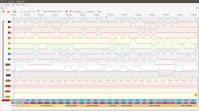
It's possible to capture the same data graphically using pulseview:
Attachment:
sigrok20.png
sigrok20.png [ 187.68 KiB | Viewed 12236 times ]

Zooming in slightly, you can see we have annotated individual bus cycles.
Attachment:
sigrok21.png
sigrok21.png [ 138.37 KiB | Viewed 12236 times ]

You can see each instruction starts with a fetch cycle, followed by optional operands, then finally any memory accesses. At least most of the time, as JSR is a little different. You can also see that the Master makes use of RDY to extend reads and writes to certain I/O addresses.

What's quite neat here is that even without any connection to the address bus, the protocol decoder very quickly starts predicting what the current program counter value would be. The algorithm for doing that (mostly down to Ed) is here.

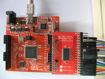
In terms of capture hardware, this should work with anything that is supported by Sigrok that has at least 12 channels and can sample at ~5x the CPU speed. I've tried out a couple of different logic analyzer implementations:

The first was a version Open Bench Logic Sniffer that I recompiled for my Papilio One FPGA board:
Attachment:
IMG_1121.JPG
IMG_1121.JPG [ 443.19 KiB | Viewed 12236 times ]

This supports sampling at up to 200MHz, and allows for synchronous sampling (where Phi2 is used as the sample clock). But it stores samples in FPGA block RAM, so the capture depth is quite limited (a couple of thousand instructions).

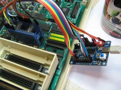
The second was a cheap (£12.49 from here) Cypress FX2 development board:
Attachment:
IMG_1124.JPG
IMG_1124.JPG [ 473.68 KiB | Viewed 12236 times ]

This streams data directly to host memory, so supports much longer captures. But it's limited to 12MHz sampling, and doesn't support synchronous sampling. I've successfully captured in excess of 2 million 6502 cycles, which is more than enough for the complete startup of the BBC Micro.

Both interfaces work very well in practice, and the 6502 protocol decoder supports both synchronous and asynchronous sampling (based on whether Phi2 is wired up or not). A decent 40-pin DIP clip is highly recommended, as most cheap test grabbers are absolutely rubbish.

The source code for the protocol decoder is available in github:
https://github.com/hoglet67/libsigrokde ... rs/mos6502

I can't really overstate how useful a tool like is can be in diagnosing misbehaving 6502 systems (old or new). If anyone wants to have a play, I'm quite happy to help answer any questions. Deployment should just be a case of copying these three files into the right place in your sigrok installation. There are a few more details in the stardot posts (linked above)

Dave


Last edited by hoglet on Tue Mar 13, 2018 2:38 pm, edited 3 times in total.

Top
 Profile  
Reply with quote  
PostPosted: Fri Oct 27, 2017 7:27 pm 
Offline
User avatar

Joined: Thu Dec 11, 2008 1:28 pm
Posts: 10793
Location: England
Excellent project Dave - I'm happy to have had a small part in it. I'm sure it's a major step forward in being able to diagnose faults and bugs in 6502 systems, or just to better understand what they are doing.

As an illustration, earlier this week we had a look at the boot sequence of the BBC Micro, hoping to find something completely deterministic. Diffing a couple of captures, we first noticed that the system timer needed to be initialised, so we switched to a cold boot by poking the VIA before hitting reset. There was still a difference, and it turned out to be the timing of the Vertical Sync interrupt, which comes from the CRTC which, it turns out, is not reset by the main reset signal on the board. So, the third effort was to capture from a cold power-on - and this time two captures did match, all the way from reset to the prompt.

Other interesting things we've seen, mentioned I think in your Stardot thread, are the clock-stretching on the BBC Micro when it accesses a slow peripheral - and we could see exactly which cycle of which instruction caused that - and the RDY line doing the same job on the BBC Master. It was also interesting to see the sequence of events on interrupts, and to see how long it sometimes takes to service an interrupt, and to see the CLI/SEI sequence in the MOS, presumably psuedo-polling for an outstanding interrupt while in the middle of handling something time-consuming.


Top
 Profile  
Reply with quote  
PostPosted: Sun Oct 29, 2017 8:09 am 
Offline

Joined: Wed Feb 12, 2014 1:39 am
Posts: 172
Location: Sweden
This is fantastic! I especially like the fact that no address bus connection is needed. Good work!


Top
 Profile  
Reply with quote  
PostPosted: Sun Oct 29, 2017 12:08 pm 
Offline

Joined: Sun Jun 29, 2014 5:42 am
Posts: 337
Thanks all for the positive comments!

Currently we're able to infer the value of the program counter by just watching the data bus. Could this be extended to other registers, such as the stack pointer?

The following instructions modify the stack pointer by adding or subtracting a constant value:
- JSR
- RTS
- RTI
- BRK (and other interrupts)
- PHA/PHX/PHY/PHP
- PLA/PLX/PLY/PLP

So if you know the initial value, you can track all subsequent changes resulting from these instructions.

But the only instruction that sets the stack pointer to an arbitrary value is TXS. So it seems that to determine the initial value of the stack pointer you would need to have captured a TXS, and also known what the value of X was.

There are some cases where this is clearly possible. For example, if you captured the following sequence:
Code:
LDX #&FF
TXS

You now know the value of the stack pointer, and can track the subsequent relative changes.

But doing this is the general case seems hard, and I think you end up having to effectively emulate the 6502 inside the protocol decoder (which may well be useful).

So maybe it would be better to allow a connection to the address bus (even just A7..A0 would be useful) and accept that certain features are only possible if this is present.

I'd love to get some other peoples thoughts on this.


Top
 Profile  
Reply with quote  
PostPosted: Sun Oct 29, 2017 12:12 pm 
Offline
User avatar

Joined: Thu Dec 11, 2008 1:28 pm
Posts: 10793
Location: England
An interesting thought that you only need the bottom byte to be able to decode any stack access! Indeed, even if you just traced the bottom nibble, that could allow for some useful readout of subroutine depth.
JSR [S=?D]
PHA [S=?B]
JSR [S=?9]
RTS [S=?B]
PLP [S=?D]
RTS [S=?F]


Top
 Profile  
Reply with quote  
PostPosted: Sun Oct 29, 2017 12:38 pm 
Offline
User avatar

Joined: Thu Dec 11, 2008 1:28 pm
Posts: 10793
Location: England
Another thought: for purposes of tracking call depth and other use of the stack, you mostly care about relative stack depth, not absolute. So some fictitious stack depth report might be useful:
JSR [S=?-102]
PHA [S=?-103]
JSR [S=?-105]
RTS [S=?-103]
PLP [S=?-102]
RTS [S=?-100]
(Not sure how best to represent that, especially tersely.)

There are also many calls to TSX in the trace of the BBC Micro boot sequence, but X is then used to index into page 1 and X is typically overwritten soon after.

As you might expect, there's only the single call to TXS, so any modelling of X which is more sophisticated than looking for LDX #FF wouldn't gain anything, in this case. (Any load or any store of X would make it a known value, but TAX and TSX could make it unknown again.)


Top
 Profile  
Reply with quote  
PostPosted: Sun Oct 29, 2017 7:56 pm 
Offline
User avatar

Joined: Fri Dec 11, 2009 3:50 pm
Posts: 3346
Location: Ontario, Canada
hoglet wrote:
So maybe it would be better to allow a connection to the address bus (even just A7..A0 would be useful) and accept that certain features are only possible if this is present.

I'd love to get some other peoples thoughts on this.

If I were in your place it would forever bother me if "certain features are only possible if this is present." Connections to the address bus are both practically problematic and theoretically unnecessary. I'd be irresistibly drawn to emulating the 6502 and eliminating the need for those connections!

OTOH I admit I've had projects which never got completed because the list of features couldn't be constrained. :oops:

Maybe it's best to begin by assessing the difficulty. Certainly there's a fair amount of detail to cover, but it's not an intrinsically gnarly problem like cycle-accurate interrupt behavior. All we need is an accurate picture of what's in X. That means the other registers would need to be tracked, too -- lots of detail, as I said.

Congrats to Dave & Ed on a very intriguing project! Naturally (since it's your time at stake, not mine) I vote for you to add the shiny, new feature! :D :wink:

-- Jeff

_________________
In 1988 my 65C02 got six new registers and 44 new full-speed instructions!
https://laughtonelectronics.com/Arcana/ ... mmary.html


Top
 Profile  
Reply with quote  
PostPosted: Sun Oct 29, 2017 8:17 pm 
Offline
User avatar

Joined: Thu Dec 11, 2008 1:28 pm
Posts: 10793
Location: England
I don't think it would be too difficult - just perhaps tedious, as you imply - to track A, X and Y. It's a pity that S poses a different kind of challenge. Initially I thought a slightly modified emulator would do most of the work, but a little more thought told me that there's more difference than just a little. It's not entirely unlike an emulator, but there's a lot of change.

(I did wonder for a little while if a very clever program could figure out the instruction fetch pattern without seeing SYNC, but I think it's usually far too difficult and sometimes impossible.)


Top
 Profile  
Reply with quote  
PostPosted: Sun Oct 29, 2017 9:38 pm 
Offline

Joined: Sun Jun 29, 2014 5:42 am
Posts: 337
I think it is worth trying to extend the protocol decoder to mirror all of the remaining 6502 state (A, X, Y, SP, flags).

But there are cases when you will be able to do better with a connection to the address bus.

Take the stack pointer for example. If you have a connection to the address bus, then you can determine the current SP value at the first instruction that makes use of the stack. Without this, you have to wait for a TXS or a TSX, which may never occur.

That said, the most common usage of a gadget like this is to diagnose a system that's failing to boot properly. And one of the first things that should happen is the stack pointer being initialised with a TXS.

I also think this is easier than a full emulator, as you don't have to model memory or changes of control flow. And you can probably collapse all the different addressing modes down to "the last read value on the bus".

The only other concern is performance, as currently post-processing ~1 second of real 6502 time (12 million samples @ 12MHz) takes about a minute on my system. But in sigrok we can make "track all state" an option that can be enabled or disabled as needed, and when disabled there should be minimal impact.


Top
 Profile  
Reply with quote  
PostPosted: Mon Oct 30, 2017 11:28 am 
Offline
User avatar

Joined: Thu Dec 11, 2008 1:28 pm
Posts: 10793
Location: England
Perhaps a better idea for fictitious stack depth report:
Code:
JSR [S=?? (-2)]
PHA [S=?? (-3)]
JSR [S=?? (-5)]
RTS [S=?? (-3)]
PLP [S=?? (-2)]
RTS [S=?? (0)]
LDX #FF
TXS [S=FF]

where the ?? stand for the hex value which is not presently known, and the number in parenthesis is the offset since the trace started. Once the stack value is known, you probably don't want that offset any more. So perhaps better would be two different presentations, like this:
Code:
PHA [S=(-1)]
LDX #FF
TXS [S=FF]

or to make it more clear when S is unknown
Code:
PHA [S=?-1?]
LDX #FF
TXS [S=FF]


Top
 Profile  
Reply with quote  
PostPosted: Sat Nov 04, 2017 5:59 pm 
Offline
User avatar

Joined: Fri Dec 11, 2009 3:50 pm
Posts: 3346
Location: Ontario, Canada
hoglet wrote:
The 6502 protocol decoder requires just 12 signals plus ground to be connected: D7..D0, RnW, Sync, Rdy and Phi2.
For what it's worth, you might consider capturing A0 (the LS address line). A0 will give you the earliest possible indication that an interrupt is being recognized. It's a truism that the address bus always increments following an opcode fetch (ie, sync cycle) but the increment will be absent (and A0 will remain unchanged) if the opcode just fetched is discarded. (Internally the discarded opcode gets replaced with a BRK, more or less).

I assume you're presently detecting interrupts by watching for three consecutive writes (which will be PC and P being pushed to stack). That works, too, of course, but there's more delay before the interrupt becomes apparent. Is that important? I don't know.

On a slightly different topic, if you capture A0 then it becomes unnecessary to capture RnW (as it can be inferred from the opcode and the cycle count). But there may possibly be value in having both.

-- Jeff

_________________
In 1988 my 65C02 got six new registers and 44 new full-speed instructions!
https://laughtonelectronics.com/Arcana/ ... mmary.html


Top
 Profile  
Reply with quote  
PostPosted: Sat Nov 04, 2017 6:39 pm 
Offline

Joined: Sun Jun 29, 2014 5:42 am
Posts: 337
Hi Jeff,
Dr Jefyll wrote:
For what it's worth, you might consider capturing A0 (the LS address line). A0 will give you the earliest possible indication that an interrupt is being recognized. It's a truism that the address bus always increments following an opcode fetch (ie, sync cycle) but the increment will be absent (and A0 will remain unchanged) if the opcode just fetched is discarded. (Internally the discarded opcode gets replaced with a BRK, more or less).

That's very interesting, I wasn't aware of that.
Dr Jefyll wrote:
I assume you're presently detecting interrupts by watching for three consecutive writes (which will be PC and P being pushed to stack). That works, too, of course, but there's more delay before the interrupt becomes apparent. Is that important? I don't know.

Yes, that how it's currently done. The delay doesn't really matter, as we are doing the processing on the next sync anyway.

I haven't yet tackled the next stage of this yet, the tracking of register state (A, X, Y, SP, Flags). I've convinced myself it is possible, but I've got a bit side tracked by another fun project.

Dave


Top
 Profile  
Reply with quote  
PostPosted: Wed Nov 08, 2017 1:51 pm 
Offline
User avatar

Joined: Thu Dec 11, 2008 1:28 pm
Posts: 10793
Location: England
hoglet wrote:
I think it is worth trying to extend the protocol decoder to mirror all of the remaining 6502 state (A, X, Y, SP, flags).
...
I also think this is easier than a full emulator, as you don't have to model memory or changes of control flow. And you can probably collapse all the different addressing modes down to "the last read value on the bus".

Not so sure about 'last value' - for loads and stores, you do get the register value from the bus access. In the case of load you also get flags N and Z. For ALU operations you need to combine the reg value with the bus value to get any information. For RMW you don't get any reg values but the bus value gives you N and Z. For branches you do get a flag value. So, I think there are a few cases. I think I'd start with the data representation: probably A and A_known, X and X_known, Z and Z_known, and so on. In C you'd probably use a struct, but in Python I'd probably just use pairs of variables - performance being a bit of an issue - otherwise perhaps a set of dicts: A[value] and A[known] and so on, but I don't think that buys you much.


Top
 Profile  
Reply with quote  
PostPosted: Wed Nov 08, 2017 2:36 pm 
Offline

Joined: Sun Jun 29, 2014 5:42 am
Posts: 337
Hi Ed,

I think we are on the same page there. I wasn't suggesting that the last value on the bus was all that was needed. You do need to model the ALU and flag setting logic, exactly like an emulator would. All I was saying was that the different addressing modes collapse together. So for example, take the various forms of ADC:
- ADC #&xx
- ADC &xx
- ADC &xx,X
- ADC &xx,Y
- ADC &xxxx
- ADC &xxxx,X
- ADC &xxxx,Y
- ADC (&xx)
- ADC (&xx),Y
- ADC (&xx, X)

All of these collapse down to a common "ADC" implementation, and the operand will be the final read cycle of the instruction. The addressing mode I think is mostly irrelevant.

The only exception I can think of where the flags are set differently in one addressing mode is BIT #&00 vs the other forms of BIT. Can you think of any others?

Anyway, you have prompted me to make a start this afternoon!

Dave


Top
 Profile  
Reply with quote  
PostPosted: Wed Nov 08, 2017 4:40 pm 
Offline
User avatar

Joined: Thu Dec 11, 2008 1:28 pm
Posts: 10793
Location: England
Ah, yes, very good point: it does collapse down the number of things to handle. (I think BIT is the only one. It's also true that TXS doesn't set the flags, unlike the other Txx operations.)


Top
 Profile  
Reply with quote  
Display posts from previous:  Sort by  
Post new topic Reply to topic  [ 48 posts ]  Go to page 1, 2, 3, 4  Next

All times are UTC


Who is online

Users browsing this forum: No registered users and 6 guests


You cannot post new topics in this forum
You cannot reply to topics in this forum
You cannot edit your posts in this forum
You cannot delete your posts in this forum
You cannot post attachments in this forum

Search for:
Jump to: