6502.org Forum  Projects  Code  Documents  Tools  Forum
It is currently Thu May 02, 2024 11:30 am

All times are UTC


Post new topic Reply to topic  [ 115 posts ]  Go to page Previous  1, 2, 3, 4, 5 ... 8  Next
Author Message
PostPosted: Mon Oct 09, 2017 2:10 pm 
Offline
User avatar

Joined: Fri Nov 09, 2012 5:54 pm
Posts: 1392
Tried to stick with the concept of using pre_formatted data for the sprites, too.
This would require two shift registers 24 Bit each plus three latches 8 Bit per sprite...

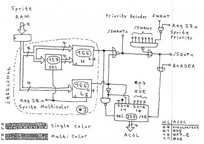
Note, that the serial input of the 74166 shift registers is tied to GND.

If we assume, that nobody would be switching the sprites between "normal" and multicolor
within a raster line, we even could make use of the pre_formatting data multiplexers
in the previous schematic.

For "single color", the L shift register is forced to zero.
Dang, that scanner had switched to monochrome... just take a look at the blue marked
data Bit patterns at the previous page.

That 7430 with the /SWANT signals is for building a sprite display priority decoder.
With /SWANT=0, the sprite says "I want priority".
With /SGOT=0, the sprite says "I got priority".


In theory, one could go without the latches by building 25 Bit shift registers,
means three 74166s and a 7474 at the output in a row.
The trick is to clear the 7474 when loading the 74166s.
But this concept probably would require clock gating...

Attachment:
v2_9.jpg
v2_9.jpg [ 137.02 KiB | Viewed 1234 times ]


Would suggest to build 8 identical modules (that also contain the X/Y comparators etc.), one for each sprite.

Ok, and with this we are "almost" through with the hot part of the VIC-II. :mrgreen:
Will try to add the wiring for the sprite display priority decoder and the sprite/sprite collision detection later... but now I need a break.


Top
 Profile  
Reply with quote  
PostPosted: Mon Oct 09, 2017 2:38 pm 
Offline

Joined: Sat May 02, 2015 6:59 pm
Posts: 134
ttlworks wrote:
Thanks, Cray Ze:
Using the upper 4 Bits of an 8 Bit color RAM for displaying something _different_ than color with them
is a nice idea, and I haven't noticed that possibility for "compacting" a picture. :)

Would be nice, if you could elaborate this more into detail...
I'm just going to need to post two more schematics pictures now to prevent some details from "slipping from my brain".


I made an edit to my first post above, though it's mentioned again here.

It just popped into my head when thinking about how one could increase resolution without taking up more address space. The thinking was along the lines of controlling either address lines or chip-selects with the extra bits, while not thinking too much about the decode logic required to do so. The RAM bank to fetch from would be auto selected for every 8x8 pixel block in the same way the colour is automatically fetched. This could be used for special effects on lower resolutions where the extra 3 banks could be used to rapidly switch in any block of graphics that's a multiple of 8x8 pixels.

CPU read/writes to the banks would have to be controlled by a bank select register, as mentioned in my edit above, a VIC II light pen register makes a good candidate, there are two of them so perhaps some room for expansion :)

If you wanted a little less control, but the same high resolution and the ability to use all 8Bits of colour RAM as colour, run the same banking logic as above, driven from bits 3 and 4 of the pixel clock. This should cycle through 4 display banks at intervals of 8 pixels. Still, the issue of mapping it for CPU access exists.


Top
 Profile  
Reply with quote  
PostPosted: Mon Oct 09, 2017 4:18 pm 
Offline
User avatar

Joined: Fri Nov 09, 2012 5:54 pm
Posts: 1392
So when having 8 Bit "color RAM", the idea is to use only maybe 6 Bits for colors,
and the other two Bits for selecting from which of 4 possible 8kB banks in memory
to fetch that 8*8 pixel block to be displayed.

The CPU to be used in the C74 project would be going to have a 24 Bit address bus,
so I guess that mapping display memory to the CPU won't be too difficult...

Hmm... right, those LPX\LPY registers seem to be read_only in the VIC-II.
Hey, two 8 Bit registers would give us 4 Bits per bank that could be put on the address bus.
So when moving those banks in 8kB steps in memory, this would give us a 128kB address range
for the VIC-II.

// _If_ one would be able to move the banks with a smaller "granularity",
// the effects of partially overlapping banks might be interesting...
// especially if a big area of the picture would happen to have identical color\texture.

When using all the color RAM Bits for color, "slicing" the picture into 4 banks sounds nice.
...Of course, coders who would have to make a drawing program for those display modes
probably won't like us much. ;)


Top
 Profile  
Reply with quote  
PostPosted: Mon Oct 09, 2017 4:30 pm 
Offline
User avatar

Joined: Fri Nov 09, 2012 5:54 pm
Posts: 1392
I'm now tossing in the two remaining sheets of schematics:

An idea for a sprite display priority decoder:

Attachment:
v2_10.jpg
v2_10.jpg [ 71.13 KiB | Viewed 1217 times ]


;---

Some odd circuitry that might be (or might not be) useful for detecting sprite/sprite collision:

Attachment:
v2_11.jpg
v2_11.jpg [ 113.76 KiB | Viewed 1217 times ]


;---

And with this, that pile of scratch paper on my desk eventually went through. Woot.


Top
 Profile  
Reply with quote  
PostPosted: Mon Oct 09, 2017 6:35 pm 
Offline

Joined: Sat May 02, 2015 6:59 pm
Posts: 134
ttlworks wrote:
So when having 8 Bit "color RAM", the idea is to use only maybe 6 Bits for colors,
and the other two Bits for selecting from which of 4 possible 8kB banks in memory
to fetch that 8*8 pixel block to be displayed.
"color RAM", that name may become redundant. Yes, 6 Bits still gives you 64 colours, with the remaining 2 Bits controlling the most significant bits of a 32KB address range.
Quote:
The CPU to be used in the C74 project would be going to have a 24 Bit address bus,
so I guess that mapping display memory to the CPU won't be too difficult...

Hmm... right, those LPX\LPY registers seem to be read_only in the VIC-II.
Hey, two 8 Bit registers would give us 4 Bits per bank that could be put on the address bus.
So when moving those banks in 8kB steps in memory, this would give us a 128kB address range
for the VIC-II.
In the described/imagined scheme, the RAM bank seen by the video system is controlled by the upper 2 colour RAM bits. The CPU access to the 4 banks is controlled with 2 bits in the LPX register. This way, the bank selection is automatic and based on the colour RAM, and only CPU access to the banks requires program control. If you dedicated the entire top nybble to the decoding, you'd get 16 x 8KB banks of display data for a total of 128KB. The 8K BANK we are mapping into is located somewhere in the VIC-II's 16KB address space, you could use the other 6 Bits in the LPX register to map the entire 16KB of VIC-II address space to any of 64 locations, that would cover 1MB if not overlapped, or give finer control in a smaller address range, if overlapped. This is something separate to the 8KB display mapping, though the 8KB range would be mapped along with it.

Of course, upon rereading your post, I think I've basically described the same thing anyway, or something very similar.
Quote:
// _If_ one would be able to move the banks with a smaller "granularity",
// the effects of partially overlapping banks might be interesting...
// especially if a big area of the picture would happen to have identical color\texture.

When using all the color RAM Bits for color, "slicing" the picture into 4 banks sounds nice.
...Of course, coders who would have to make a drawing program for those display modes
probably won't like us much. ;)

It's probably not that much of a problem, VIC-II programmers have never had the luxury of a linear framebuffer so there was always quirks, look at multicolour bitmap mode for the most fun.


Top
 Profile  
Reply with quote  
PostPosted: Tue Oct 10, 2017 6:00 am 
Offline
User avatar

Joined: Fri Nov 09, 2012 5:54 pm
Posts: 1392
When spending some more thoughts on this:

If there would be enough bandwidth on the bus, I think there would be another
interesting use for those 4 uppermost color RAM Bits.

A pointer in the VIC-II that is going to be re_initialized during vertical sync.

At the end of displaying 8 pixels in a raster line from an 8*8 block,
the 4 Bits could tell the VIC:
for one specific raster line of that 8*8 block,
or for all of the raster lines of that 8*8 block,
take two Bytes from a table in memory, write the first Byte into a VIC register
selected by the second Byte, then increment the pointer.

Won't be as advanced/comfortable as the Copper in the Amiga, of course...


Top
 Profile  
Reply with quote  
PostPosted: Tue Oct 10, 2017 7:25 am 
Offline

Joined: Sat May 02, 2015 6:59 pm
Posts: 134
It sounds interesting, though it does have a rather 'Rubik's Cube' feel to it from a programming point of view. HiRes mode could still be achieved using this method by writing into a register that would change where display RAM comes from. Implementation could be tricky.
Quote:
At the end of displaying 8 pixels in a raster line...
I might be missing something here, but at the end of displaying 8 pixels, those pixels are already on the display and no amount of magic will change them.

I had thought of other uses for the 4 Bits, like using one of them to disable sprite-background collision for the 8x8 block, which would help in coding hardware collision detection routines (many people use software based bounding boxes because the hardware is somewhat lacklustre). When you don't care about collisions with a certain graphic, setting the bit could disable collision and you don't have to handle the case in the collision detection code, which wouldn't have to run in this case as no interrupt would be generated to trigger it. Something similar could be done with sprite-background priority ber 8x8 block, saving code in checking if a sprite should be in front of, or behind certain graphics.

At this point, I'm wondering if the 4 Bit restriction we have could be bypassed with a parallel address space. An extra 8 Bits could allow for some very interesting possibilities.


Top
 Profile  
Reply with quote  
PostPosted: Tue Oct 10, 2017 8:36 am 
Offline
User avatar

Joined: Fri Nov 09, 2012 5:54 pm
Posts: 1392
Quote:
It sounds interesting, though it does have a rather 'Rubik's Cube' feel to it from a programming point of view.

Most certainly yes.

Quote:
HiRes mode could still be achieved using this method by writing into a register that would change where display
RAM comes from. Implementation could be tricky.

Especially when taking Video address Bit 14 and 15 into account...

Quote:
I might be missing something here, but at the end of displaying 8 pixels, those pixels are already on the display
and no amount of magic will change them.

Fetching two Bytes from memory sure takes some time...
So my idea was defining the action to be taken one 8*8 pixel block ahead, what sure increases that 'Rubik's Cube' feel, sorry.

Quote:
I had thought of other uses for the 4 Bits, like using one of them to disable sprite-background collision
for the 8x8 block, which would help in coding hardware collision detection routines
(many people use software based bounding boxes because the hardware is somewhat lacklustre).
When you don't care about collisions with a certain graphic, setting the bit could disable collision
and you don't have to handle the case in the collision detection code, which wouldn't have to run
in this case as no interrupt would be generated to trigger it.
Something similar could be done with sprite-background priority ber 8x8 block, saving code in checking
if a sprite should be in front of, or behind certain graphics.

Collision detection and display priority, sounds like a very useful feature. Nice.

Quote:
At this point, I'm wondering if the 4 Bit restriction we have could be bypassed with a parallel address space.
An extra 8 Bits could allow for some very interesting possibilities.

Now this sounds like having 16 Bits of color RAM...


Top
 Profile  
Reply with quote  
PostPosted: Tue Oct 10, 2017 8:58 am 
Offline

Joined: Sat May 02, 2015 6:59 pm
Posts: 134
ttlworks wrote:
Now this sounds like having 16 Bits of color RAM...
You mean "Display Mode RAM" of course :D
In theory, as long as those original 4 Bits do what they always did when all other bits are zero, you don't lose compatibility with the original VIC-II, no matter how wide you go.


Top
 Profile  
Reply with quote  
PostPosted: Tue Oct 10, 2017 10:10 am 
Offline
User avatar

Joined: Thu Dec 11, 2008 1:28 pm
Posts: 10793
Location: England
(It might be interesting for you to have a look at the PaletteMate aka VideoNULA project for Acorn's Beeb: it takes the existing 4bpp screen layout and makes some interesting new uses of the bitstream. There's an explanatory PDF in the zip at the link.)


Top
 Profile  
Reply with quote  
PostPosted: Tue Oct 10, 2017 12:21 pm 
Offline
User avatar

Joined: Fri Nov 09, 2012 5:54 pm
Posts: 1392
Cray Ze wrote:
You mean "Display Mode RAM" of course :D

Hmm... "attribute RAM" would be better. :)
The problem with old C64 software is, that we can't be 100% sure that the upper 4 Bits are always written with 0.
But when taking care of this...

IIRC, in the C64 during a BadLine the VIC-II fetches text RAM and 'color' RAM when PHI2=1,
and reads the character generator ROM (or graphics data) when PHI2=0.

So when having a 74573 transparent latch in front of the attribute RAM address lines that keeps the address from PHI2=1 stable during PHI2=0,
and when having PHI2 on an additional address pin of that RAM during VIC-II reads,
we _could_ read 16 Bit from a single 8 Bit attribute RAM chip within one PHI2 clock cycle.
The RAM needs to be faster than a 2114, of course.


BigEd wrote:
Acorn's Beeb

I'm not familiar with the Beeb. After a wikipedia search, it appeared to me that Beeb is the Nickname for the BBC micro...
Found some text about the video ULA of the Beeb.

;--

Found an interesting/impressive project about building a "custom" TTL CPU that generates a VGA picture.
https://hackaday.io/project/20781-breadboard-color-computer-from-ttl

Unfortunately, the VIC-II is a complicated beast.
Trying to build a 16 Bit TTL CPU "emulating" a VIC-II probably won't take less chips than a TTL implementation of the VIC-II.


Top
 Profile  
Reply with quote  
PostPosted: Tue Oct 10, 2017 1:30 pm 
Offline

Joined: Sat May 02, 2015 6:59 pm
Posts: 134
ttlworks wrote:
Cray Ze wrote:
You mean "Display Mode RAM" of course :D

Hmm... "attribute RAM" would be better. :)
The problem with old C64 software is, that we can't be 100% sure that the upper 4 Bits are always written with 0.
But when taking care of this...

IIRC, in the C64 during a BadLine the VIC-II fetches text RAM and 'color' RAM when PHI2=1,
and reads the character generator ROM (or graphics data) when PHI2=0.

So when having a 74573 transparent latch in front of the attribute RAM address lines that keeps the address from PHI2=1 stable during PHI2=0,
and when having PHI2 on an additional address pin of that RAM during VIC-II reads,
we _could_ read 16 Bit from a single 8 Bit attribute RAM chip within one PHI2 clock cycle.
The RAM needs to be faster than a 2114, of course.


That could work, and faster/larger RAM can be found for reasonable prices, often in SOJ format so a DIP adapter would be necessary.
CY7C1049D-10VXI - 4-Mbit ( 512 K × 8 ) 10ns Static RAM - US $2.77 on ebay.
http://www.cypress.com/file/42806/download
http://www.ebay.com/itm/-/181217407724

Another idea that popped into my head was along the lines of the 4 Bits being used to select any of ̶ ̶ ̶1̶6̶ ̶8̶K̶ ̶b̶a̶n̶k̶s̶ ̶ 16 1K banks of 8 Bit attribute RAM. Indirect attribute RAM if you like.


Last edited by Cray Ze on Tue Oct 10, 2017 3:58 pm, edited 1 time in total.

Top
 Profile  
Reply with quote  
PostPosted: Tue Oct 10, 2017 1:52 pm 
Offline
User avatar

Joined: Fri Nov 09, 2012 5:54 pm
Posts: 1392
Cray Ze wrote:
Indirect attribute RAM if you like.

Now this feels a little bit like re_inventing the 80386 MMU. ;)

What's the advantage of having indirect attribute RAM,
and how it is going to be used ?


Top
 Profile  
Reply with quote  
PostPosted: Tue Oct 10, 2017 5:04 pm 
Offline

Joined: Sat May 02, 2015 6:59 pm
Posts: 134
ttlworks wrote:
Cray Ze wrote:
Indirect attribute RAM if you like.

Now this feels a little bit like re_inventing the 80386 MMU. ;)

What's the advantage of having indirect attribute RAM,
and how it is going to be used ?

I went and had a sleep for an hour or so, and upon my return I see It's clear that I must have been tired.

I typed 8K where I should have typed 1K (like the standard colour RAM).
Instead of using the 4 Bits in an attempt to control various attributes, they would contol the upper four address lines of an 16K block of ram (for 16 blocks of 1K). An 8 Bit control attribute for the 8x8 block comes from it's matching location in the currently selected 1K. In the imagined scheme, the functions of the attributes would be the same for each bank (though this doesn't have to be the case). This allows for 8 Bits worth of various attribute functions that can be rapidly switched between 16 Different functions, which could be handy for games and demos depending on what functions are decided on.

The earlier discussed subjects of double resolution (using two Bits to control 4 8K display areas automatically - or go bigger with an extra Bit), sprite-background priority, and collision detection all map well to this scheme.

It was just a random thought but seemed valid, it can allow for keeping compatibility with the original 4 Bit colour RAM, and provides lots of scope more ideas.
Of course, using only two of the Bits would still allow for 4 x 1K blocks (upper 2 address lines of a 4K block of RAM) of control attributes, and leave 2 Bits spare for other use. You could just use one 1 Bit with a single 1K block of attributes.


Top
 Profile  
Reply with quote  
PostPosted: Wed Oct 11, 2017 6:16 am 
Offline
User avatar

Joined: Fri Nov 09, 2012 5:54 pm
Posts: 1392
Some ASCII art for illustrating your concept (I hope I got that right):
Code:
       $D800
       -------------------
      | 1kB Attribute RAM |
      |   *               |
       ---|---------------
          |$D803 //example
          v
   Attribute_RAM Byte
   7654 3210
   ---- ----
  |iiii|cccc|  1111.0110 //example: iRam_block=F, color=blue
   ---- ----
    |    |
    |    v
    |   16 Colors (C64)
    |
    |       $0000,$4000,$8000,$C000
    |       --------------------
     ---> 0| 1kB iAttribute RAM |
           |                    |
            --------------------
          1| 1kB iAttribute RAM |
           |                    |
            --------------------
            ...              ...
            --------------------
          F| 1kB iAttribute RAM |
           |   *                |
            ---|----------------
               |$3C03 //example
               v
       iAttribute_RAM Byte
       76543210
       --------
      |  foo   |
       --------


I think, in your concept the VIC-II would have to do an additional main memory access per character...


Top
 Profile  
Reply with quote  
Display posts from previous:  Sort by  
Post new topic Reply to topic  [ 115 posts ]  Go to page Previous  1, 2, 3, 4, 5 ... 8  Next

All times are UTC


Who is online

Users browsing this forum: JohanFr, rwiker and 8 guests


You cannot post new topics in this forum
You cannot reply to topics in this forum
You cannot edit your posts in this forum
You cannot delete your posts in this forum
You cannot post attachments in this forum

Search for:
Jump to: