Hi guys
I'm still working on my 65C02GPD v2 design, having "fun" routing it all atm

.
While looking at the datasheet for the
MCP7940N (I2C RTCC which I plan to incorporate) I noticed that it recommends surrounding the 32KHz crystal/can used for timing with a pour which is grounded.
This should encompass the oscillator circuit entirely (see below) and no traces should be run underneath (same layer or any other layer).
Is this something that I should be doing for my main PHI2 source? I tend to have that as a DIL socket-ed can which then runs to a D type flipflop. I.e. should I be doing away with the socket?
I also found some advice which says that if this is done I should put a pour underneath the can on the top layer (this is a layer 4 PCB - middle two layers are GND and VCC) and on the bottom layer, link both to the GND layer then solder the chassis of the can to both pours.
If so, is capacitance an issue here?
Again, is this something that you guys tend to bother with? I assume to avoid noise on the PCB from the crystal/can?
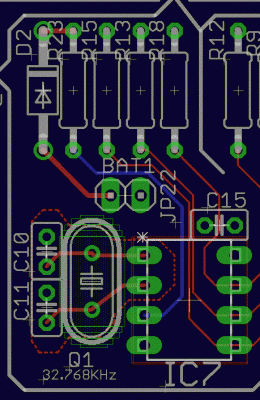
This is what I've done with regards the RTCC so far:
Attachment:
 Capture.GIF [ 53.18 KiB | Viewed 3110 times ]
IC7 is the MCP7940N
The red dotted somewhat asymmetric area is the top layer pour which is linked to the ground plane via the cathodes of the two capacitors C10 & C11. I haven't yet added a bottom layer one.
Any thoughts/advice welcome


