6502.org Forum  Projects  Code  Documents  Tools  Forum
It is currently Tue Apr 23, 2024 6:59 pm

All times are UTC


Post new topic Reply to topic  [ 18 posts ]  Go to page 1, 2  Next
Author Message
PostPosted: Thu Mar 02, 2017 10:14 pm 
Offline
User avatar

Joined: Thu Dec 11, 2008 1:28 pm
Posts: 10793
Location: England
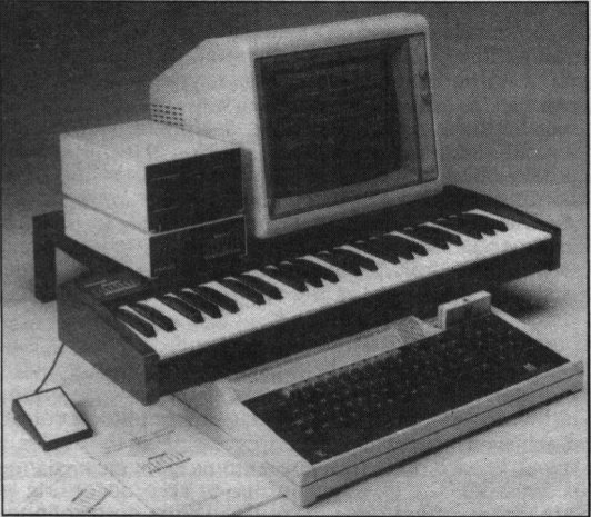
I spent the afternoon today with Dave/hoglet, digging through some mysteries in the Music 5000.

It struck me as a very interesting bit of hardware - not that we have one, although there are some around, instead we were looking at and listening to Dave's FPGA model, the published 
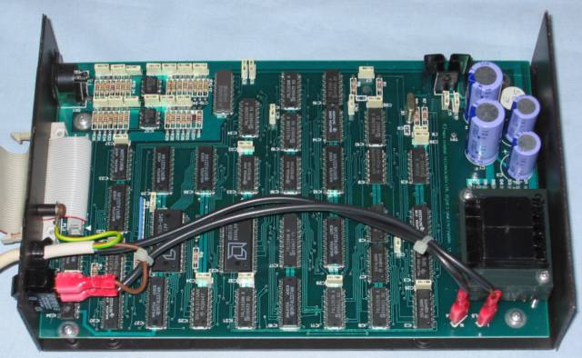
schematics for the Issue 1 board, and the software model for this synthesiser in the B-em BBC Micro emulator.

ETI article about the instrument, by Chris Jordan who designed it:
Image

Image

Quote:
The synthesiser uses a pipelined, fixed-program digital signal processor constructed largely from LS TTL devices. It runs at six million instruction cycles per second (requiring 120ns RAM access time) and uses 8-bit data words. The program computes and outputs each channel sample in eight instruction cycles (1.2us), and since there are 16 channels, this gives a total program loop time of 19.2us.


Some highlights:
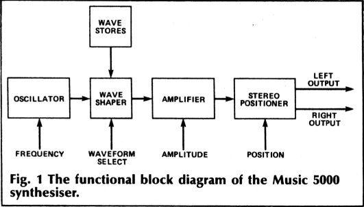
- high quality phase-accumulating wavetable synthesiser, 16 note polyphonic.
- low part count, all TTL with two RAMs, plus a DAC.
- very clever logical design: free-running 8-beat state machine at 6MHz producing 47kHz samples.
- two-nibble adder does the 24-bit phase accumulation and 8-bit gain control (in the logarithmic domain)
- companding DAC converts from 8 bits of sign+logarithm to audio output, giving 12 bits of output quality.
- very nice schematic.
- it's an 8-bit peripheral, occupying 257 addresses in the 1MHz bus area of the Beeb's memory map - one address is 'owned' and the other 256 can be shared with other peripherals.
- as such, it could attach to many 6502 systems or other 8-bit micros.
- the interface is memory-mapped, with a command byte which maps in one page of a 2k RAM.
- the RAM is write-only for the host, with a single config page and the rest to write the 14 wavetables.

Much more info in Dave's wiki here.

Image

Thanks to Chris Jordan for encouraging the investigations.

Oh, a couple of videos demoing the Music 5000:
https://www.youtube.com/watch?v=snjSIG7bb5U
https://www.youtube.com/watch?v=3S54O2ecRAY


Last edited by BigEd on Thu Mar 02, 2017 10:35 pm, edited 1 time in total.

Top
 Profile  
Reply with quote  
PostPosted: Thu Mar 02, 2017 10:23 pm 
Offline
User avatar

Joined: Thu Dec 11, 2008 1:28 pm
Posts: 10793
Location: England
Just to add: the 16 channels are added by being time-multiplexed into the DAC, which is driven at 16x the advertised sample rate.

And, the stereo panning is done by pulse-width modulating whether a sample goes into the DAC or whether a zero goes in, on successive beats of the 6MHz clock.

And, the companding DAC/ADC is used to drive stereo by using the ADC mode as a second DAC channel - it's meant to be used as a binary-search ADC.


Top
 Profile  
Reply with quote  
PostPosted: Sat Mar 04, 2017 12:16 am 
Offline

Joined: Thu Jan 21, 2016 7:33 pm
Posts: 269
Location: Placerville, CA
That's quite cool! Sounds like a cross between the Fairlight's synthesizer facilities and Konami's SCC chip. I'm curious how the noise is being produced in those demos, since the wiki mentions nothing about a noise generator - is it using heavy FM to create a pseudo-white noise sound?


Top
 Profile  
Reply with quote  
PostPosted: Sat Mar 04, 2017 6:47 am 
Offline
User avatar

Joined: Thu Dec 11, 2008 1:28 pm
Posts: 10793
Location: England
I think channel modulation is heavily used - although there are 16 phase accumulators, they appear to be presented, mostly, as 8 voices, so the software and presets seem generally to use paired oscillators. Either they are used in tandem to produce a richer tone, or one will modulate the other.

I haven't fully understood what the modulation can and can't do - it's not FM in the Yamaha sense, as far as I can tell, it uses only the sign bit of the modulating channel to swap the target channel between one configuration and another. That could be as often as many times a cycle or as seldom as some tens of cycles. (At even lower modulation rates, it could be done by the controlling software, which is how envelopes are managed.)

Or, possibly, I've misunderstood what the hardware can do... page 70 of the manual implies that the FM mode can do a lot.

Attachment:
File comment: page 70
FrequencyModulation.png
FrequencyModulation.png [ 145.21 KiB | Viewed 20946 times ]


Quote:
There are three types of modulation available: ring modulation, synchronisation, and frequency modulation.

(When it says "available", that's a combination of what the hardware can do, and what the included software offers.)

Attachment:
File comment: page 62
Instruments.png
Instruments.png [ 77.09 KiB | Viewed 20946 times ]


At least one of the samples used is a noise waveform.

The user manual (here) talks about an RM mode - ring modulation. But there is no true multiplication possible: what there is, is the ability to use the sign bit of the controlling channel to invert the controlled channel. I suppose it must be that this is a musically useful approximation.

Quote:
Ring modulation of a complex wave is one way of making random noise. The best waveform for this is "Metal", which is itself random.


Attachment:
File comment: page 69
Noise.png
Noise.png [ 129.82 KiB | Viewed 20946 times ]


The software is mostly controlled in text, it's almost like a Forth, the manual speaks of defining words.

Attachment:
File comment: page 65
Modifications.png
Modifications.png [ 121.09 KiB | Viewed 20946 times ]


Attachment:
File comment: page 66
Drum.png
Drum.png [ 149.2 KiB | Viewed 20946 times ]


Top
 Profile  
Reply with quote  
PostPosted: Sat Mar 04, 2017 6:50 am 
Offline

Joined: Sun Jun 29, 2014 5:42 am
Posts: 337
commodorejohn wrote:
That's quite cool! Sounds like a cross between the Fairlight's synthesizer facilities and Konami's SCC chip. I'm curious how the noise is being produced in those demos, since the wiki mentions nothing about a noise generator - is it using heavy FM to create a pseudo-white noise sound?

You are right, there is nothing in the hardware like a PRBS based noise generator.

But one of the "standard" waveforms looks very noise-like:
Attachment:
WAVE06.gif
WAVE06.gif [ 260.77 KiB | Viewed 20945 times ]

The full set of "standard" waveforms is on the wiki:
https://github.com/hoglet67/Music5000/wiki

Dave


Top
 Profile  
Reply with quote  
PostPosted: Sat Mar 04, 2017 9:25 am 
Offline
User avatar

Joined: Thu Dec 11, 2008 1:28 pm
Posts: 10793
Location: England
Have you any idea Dave, what the system is doing to offer a variable-depth frequency modulation? I can't see that the hardware is any help, unless one channel's output value can be added into the low byte of the next channel's phase update - and even then, I can't see how the depth could vary. Software could manage FM at some rate, but I don't know if it could keep up at an audio rate, and I don't see any way for the software to synchronise phase with the hardware.


Top
 Profile  
Reply with quote  
PostPosted: Sat Mar 04, 2017 11:19 am 
Offline

Joined: Sun Jun 29, 2014 5:42 am
Posts: 337
BigEd wrote:
Have you any idea Dave, what the system is doing to offer a variable-depth frequency modulation? I can't see that the hardware is any help, unless one channel's output value can be added into the low byte of the next channel's phase update - and even then, I can't see how the depth could vary. Software could manage FM at some rate, but I don't know if it could keep up at an audio rate, and I don't see any way for the software to synchronise phase with the hardware.

I think it must be all done in software.

Take a look at the section in the Music 5000 User Manual titled "Making Instruments":
http://www.retro-kit.co.uk/user/custom/ ... df#page=59

The notion of pitch and amplitude envelopes has to be 100% software.

One think I noticed yesterday when I was gathering that peak level data is that the values were varied each time you played a track.
I think this is possibly because it doesn't seem possible to write to the phase accumulators from the host. Or if it is, I haven't discovered how to do this. They don't seem to appear in the memory map.

There doesn't seem to be a need for synchronization between the hardware and the host. I think because the pitch and amplitude envelopes will be many 10s or 100s of cycles long.

Dave


Top
 Profile  
Reply with quote  
PostPosted: Sat Mar 04, 2017 11:28 am 
Offline
User avatar

Joined: Thu Dec 11, 2008 1:28 pm
Posts: 10793
Location: England
It might be interesting to see what an FM sound looks like from this device: if, say, a sawtooth was chosen for both the channels, we could maybe read off what's happening.

I can see FM at the millisecond level working by software. (If it is software, does it need the controlling channel at all??)


Top
 Profile  
Reply with quote  
PostPosted: Sat Mar 04, 2017 5:06 pm 
Offline

Joined: Thu Jan 21, 2016 7:33 pm
Posts: 269
Location: Placerville, CA
BigEd wrote:
Or, possibly, I've misunderstood what the hardware can do... page 70 of the manual implies that the FM mode can do a lot.

Quote:
There are three types of modulation available: ring modulation, synchronisation, and frequency modulation.

Yeah, that sounds a lot more like proper FM (or phase modulation, which works out to the same thing in the end.) Though I'm curious as to what that switching mode thing is like as well.

Quote:
At least one of the samples used is a noise waveform.

Yeah, I saw that in hoglet's post as well. What gets me is that, at only 128 samples long, the noise should sound a lot more periodic (for those familiar with NES music, "periodic noise" sounds more metallic than white-noise-ey - think the Metal Blade sound effect in Megaman 2.) Unless they're running it at a much lower rate...?

Quote:
The user manual (here) talks about an RM mode - ring modulation. But there is no true multiplication possible: what there is, is the ability to use the sign bit of the controlling channel to invert the controlled channel. I suppose it must be that this is a musically useful approximation.

This is what the SID does for its ring-modulation as well. Reminds me of a lot of non-modular analog synthesizers, where instead of a proper ring modulator they cheaped out with a XOR gate connected to the square-wave outputs of the two oscillators because with rectangular pulse waveforms that amounts to the same thing :D

BigEd wrote:
Have you any idea Dave, what the system is doing to offer a variable-depth frequency modulation? I can't see that the hardware is any help, unless one channel's output value can be added into the low byte of the next channel's phase update - and even then, I can't see how the depth could vary. Software could manage FM at some rate, but I don't know if it could keep up at an audio rate, and I don't see any way for the software to synchronise phase with the hardware.

I'm not 100% sure from a brief skim of the manual, but I'd bet that what they're doing is phase modulation. Essentially, the output of the modulator (after amplification/attenuation to allow for variable depth) gets used as an additional offset into the carrier's wavetable, causing the index (which should normally be a plain linear ramp) to cycle back and forward relative to the "true" index as the value of the modulator changes. Yamaha's FM synthesizers actually do this as well, because it's simpler and gives the same end output.


Top
 Profile  
Reply with quote  
PostPosted: Thu Sep 21, 2023 12:45 am 
Offline

Joined: Wed Sep 20, 2023 11:54 pm
Posts: 6
Belatedly...

hoglet wrote:
BigEd wrote:
Have you any idea Dave, what the system is doing to offer a variable-depth frequency modulation? I can't see that the hardware is any help, unless one channel's output value can be added into the low byte of the next channel's phase update - and even then, I can't see how the depth could vary. Software could manage FM at some rate, but I don't know if it could keep up at an audio rate, and I don't see any way for the software to synchronise phase with the hardware.

I think it must be all done in software.

Software (the M5 module) computes high and low frequencies and delivers them to the hardware's modulated channel, then hardware's modulating channel selects between high and low.

hoglet wrote:
One think I noticed yesterday when I was gathering that peak level data is that the values were varied each time you played a track.

This results from one or more of that track's instrument(s) not setting the phase - with PHSET.

hoglet wrote:
I think this is possibly because it doesn't seem possible to write to the phase accumulators from the host. Or if it is, I haven't discovered how to do this. They don't seem to appear in the memory map.

They may be written to zero by a channel control register bit and this is used by PHSET.

hoglet wrote:
There doesn't seem to be a need for synchronization between the hardware and the host. I think because the pitch and amplitude envelopes will be many 10s or 100s of cycles long.

There is very much a musical need for phase-envelope sync. See PHSET documentation.


Top
 Profile  
Reply with quote  
PostPosted: Thu Sep 21, 2023 12:57 am 
Offline

Joined: Wed Sep 20, 2023 11:54 pm
Posts: 6
commodorejohn wrote:
What gets me is that, at only 128 samples long, the noise should sound a lot more periodic (for those familiar with NES music, "periodic noise" sounds more metallic than white-noise-ey

It does. Is sounds white-noisey only when modulated.

BigEd wrote:
Have you any idea Dave, what the system is doing to offer a variable-depth frequency modulation? ... and I don't see any way for the software to synchronise phase with the hardware.

See my answers in previous reply.

BigEd wrote:
I'm not 100% sure from a brief skim of the manual, but I'd bet that what they're doing is phase modulation.

No. Frequency modulation, 1-bit.

BigEd wrote:
Essentially, the output of the modulator (after amplification/attenuation to allow for variable depth) gets used as an additional offset into the carrier's wavetable, causing the index (which should normally be a plain linear ramp) to cycle back and forward relative to the "true" index as the value of the modulator changes.

That was not affordable in 1984 due to requiring a digital multiplier.

BigEd wrote:
Yamaha's FM synthesizers actually do this as well, because it's simpler and gives the same end output.

Yamaha synths of the time used only sine waves, allowing multiplication by cheap addition through a trig identity.

Chris (Music 5000 designer)


Top
 Profile  
Reply with quote  
PostPosted: Thu Sep 21, 2023 8:54 am 
Offline

Joined: Sun Jun 29, 2014 5:42 am
Posts: 337
chrisjj wrote:
Belatedly...

Welcome Chris!

Thanks for filling in some of the blanks.

chrisjj wrote:
hoglet wrote:
I think this is possibly because it doesn't seem possible to write to the phase accumulators from the host. Or if it is, I haven't discovered how to do this. They don't seem to appear in the memory map.

They may be written to zero by a channel control register bit and this is used by PHSET.

I'm wondering if I have missed implenting this capability.

It's quite a while since I looked at this design, but I did try to write a wiki page detailing the register level interface. I don't recall any kind of a "force reset" bit in a channel's control register:
https://github.com/hoglet67/Music5000/w ... l-register

Do you recall what path in the TTL schematic was responsible for clearing a phase accumulator?

Dave


Top
 Profile  
Reply with quote  
PostPosted: Sun Sep 24, 2023 12:17 am 
Offline

Joined: Wed Sep 20, 2023 11:54 pm
Posts: 6
hoglet wrote:
I don't recall any kind of a "force reset" bit in a channel's control register


Sorry, my error. Phase set was not in the control register, but in Freq Bit 0, as your wiki correctly states.

IIRC this is not a reset (to zero) but set (to the "freq" value) though the M5 module only ever used zero.

I'd planned to use this for e.g. timbral modulation using what at the time I dubbed wave sliding, but this was precluded by pressure on host CPU and memory. Still it would be fun to implement in an updated M5.

BTW:

* "&40 unused - process access timeslot" should read "&40 unused - processor access timeslot", though since I call the Music 5000 main block a processor, perhaps (here and later) "host bus access timeslot" would be better.

* "Bit 0 Channel Disable" should read "Bit 0 Phase set", and later "Bit 0 of Frequency Lo must be zero, or the channel is disabled." likewise corrected.

* "can be used to implement a) oscillator sync (by hardware modulation) and b) gate sync, for sharp attacks (by software in the ON GATE code of the M5 module)."

should read

"is used..." I think.

* "Bit 5 Modulate Adjacent Channel" should read next channel, modulo 8 (where "next" is in register order, not the difference processing order).

Well done for this analysis!


Top
 Profile  
Reply with quote  
PostPosted: Sun Sep 24, 2023 7:15 am 
Offline

Joined: Sun Jun 29, 2014 5:42 am
Posts: 337
chrisjj wrote:
Well done for this analysis!

Thanks Chris - I've made those suggested changes

Dave


Top
 Profile  
Reply with quote  
PostPosted: Wed Sep 27, 2023 12:47 am 
Offline

Joined: Wed Sep 20, 2023 11:54 pm
Posts: 6
PS Another option as yet unused is modulating modulation. I.e. channel 1 A+B modulation ON, channel 2 A modulation ON, B OFF, channel 3. With sync this should again provide new wave-shaping - for harmonic timbral control.


Last edited by chrisjj on Thu Sep 28, 2023 11:36 pm, edited 3 times in total.

Top
 Profile  
Reply with quote  
Display posts from previous:  Sort by  
Post new topic Reply to topic  [ 18 posts ]  Go to page 1, 2  Next

All times are UTC


Who is online

Users browsing this forum: No registered users and 6 guests


You cannot post new topics in this forum
You cannot reply to topics in this forum
You cannot edit your posts in this forum
You cannot delete your posts in this forum
You cannot post attachments in this forum

Search for:
Jump to: