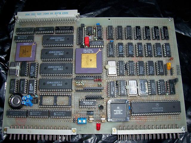
First, take a look at Oneironaut's
Vulcan 74.;---
When soldering a proto PCB:
Would suggest to use bare wire for GND and VCC.
Make sure that there are enough capacitors between GND and VCC, it's possible to solder them below the chip sockets.
And when wiring the address bus and data bus, sticking to the resistor color code simplifies debugging later.
Like: A0 -> black, A1 -> brown, A2 -> red, A3 -> yellow (had no orange wire on stock), A4 -> black again.
BTW: when using flat cables, try to make every second wire GND (like with old floppy and hard disk cables).
It's good to spend some thoughts first on how to arrange the chips on a PCB first before you start building.
Maybe it would be helpful to glue a piece of paper on top of the bigger chips describing the chip pinout.
Many years ago I had soldered my own 68020 computer: 32 Bit data bus, and at 29MHz that computer stopped to work reliable.


