6502.org Forum  Projects  Code  Documents  Tools  Forum
It is currently Fri May 10, 2024 2:12 am

All times are UTC


Post new topic Reply to topic  [ 558 posts ]  Go to page Previous  1 ... 29, 30, 31, 32, 33, 34, 35 ... 38  Next
Author Message
 Post subject: Re: TTL 6502 Here I come
PostPosted: Mon Oct 01, 2018 9:02 pm 
Offline
User avatar

Joined: Wed Mar 01, 2017 8:54 pm
Posts: 660
Location: North-Germany
A logic analyzer would be handy indeed. You could trigger on a RTI instruction while /IRQ still low (DB = $40, SYNC=1, /IRQ=0 me think).

Without a LA you may took some logic (one GAL) to generate this trigger signal and use a scope and then figure out what instructions had run before.


Regards,
Arne

EDITs: error corrected: THX to MichealM - RTI is $40 of course not $60, that is RTS ! :oops: + typo corrected :oops:


Last edited by GaBuZoMeu on Tue Oct 02, 2018 11:58 am, edited 3 times in total.

Top
 Profile  
Reply with quote  
 Post subject: Re: TTL 6502 Here I come
PostPosted: Mon Oct 01, 2018 11:48 pm 
Offline
User avatar

Joined: Mon Apr 23, 2012 12:28 am
Posts: 760
Location: Huntsville, AL
GaBoMeZeu wrote:
You could trigger on a RTI instruction while /IRQ still low (DB = $60, SYNC=1, /IRQ=0 me think).
I think that the code for RTI is 0x40.

The idea of using a CPLD (GAL) sounds pretty good, and if an in-circuit programmable one is used, it could make for a very convenient trigger for a digital oscilloscope. Pretty cool idea. Will have to remember it in the future.

_________________
Michael A.


Top
 Profile  
Reply with quote  
 Post subject: Re: TTL 6502 Here I come
PostPosted: Tue Oct 02, 2018 12:00 am 
Offline
User avatar

Joined: Fri Dec 11, 2009 3:50 pm
Posts: 3354
Location: Ontario, Canada
MichaelM wrote:
The idea of using a CPLD (GAL) sounds pretty good

It *is* a good idea, but sometimes laziness wins the day! :P Last time I tackled a problem like this I just used a 74_138. Very quick 'n easy, and the 6 inputs offer a lot of flexibility re active-high vs active-low. (Only one output was used. The whole thing was just a big NAND gate.) In some situations that will be all you need.

_________________
In 1988 my 65C02 got six new registers and 44 new full-speed instructions!
https://laughtonelectronics.com/Arcana/ ... mmary.html


Top
 Profile  
Reply with quote  
 Post subject: Re: TTL 6502 Here I come
PostPosted: Mon Oct 08, 2018 4:48 am 
Offline
User avatar

Joined: Sun Oct 18, 2015 11:02 pm
Posts: 428
Location: Toronto, ON
Holy side-effects Batman!

The crazy IRQ loops I’ve been seeing are in fact due to anomalies in dead-cycles, but the problem is not page-crossings. Rather, it’s the modify cycle of RMW instructions which is at issue — exactly the opposite of what I was hoping for when I decided to let the TTL CPU retain the 65C02’s R-R-W sequence for NMOS RMW instructions. So much for high hopes! :roll: Turns out it’s fairly common to use the NMOS R-W-W behaviour to clear interrupts on the C64.

Specifically, the VIC chip indicates the source of an interrupt by setting to “1” various bits in the Interrupt Status Register ($D019 on the C64). Writing back a “1” to the corresponding bit will clear the interrupt, and this is something that is neatly accomplished by the dead-cycle Write of an RMW instruction. The dead-cycle will write back exactly the value it read from the register in the previous cycle, which is what we want. The instruction then goes on to write the modified value in the following cycle, but by then the job is done and the interrupt is cleared.

Sadly, the side-effect is not replicated by the TTL CPU, which omits the middle Write, and may therefore fail to clear the interrupt. That is realiably so especially when using an INC instruction to clear Bit 0, which happens to be the Raster Interrupt bit, and one the most common interrupt sources on the C64. :evil: In that case, the INC will always write a “0” in Bit 0 as the final result, and without the intervening dead-cycle Write, the interrupt remains in effect.

Of course, the other interrupt sources exhibit rather more intermittent behaviour — some interrupts will clear when the INC produces a result where those bits are left as ones. Eventually, though, every interrupt source will fail to clear at one time or another, and this is exactly what happens on some games; things run quite well for a bit, and then hang with the CPU in a tight IRQ loop. There may be other problems lurking about, of course, but this seems like a plausible mechanism for the symptoms observed.

I should mention I very much appreciated all the helpful suggestions above, many of which I used in various ways to zero in on the culprit. To make a long story short, the problem became evident as soon as I saw two successive write cycles to address $D019 (the VIC Interrupt Register) on the Logic Analyzer. It sure looked like an RMW instruction at work, and sure enough, tracking back a few cycles showed the expected sequence on the data bus:

“EE 19 D0 F9 F9 FA” — where $EE is an INC abs and “F9 F9 FA” are the R-W-W cycles. For the TTL CPU, the middle cycle is a Read.

The fix, of course, is to have the TTL CPU replicate the R-W-W sequence when operating in NMOS mode. Not sure quite how to do that yet, but at least this is progress — it feels very good to track this one down! :D I’m vey eager to see whether this will fix the remaining issues on the C64 (or at least some of the remaining issues).

More to come ...

_________________
C74-6502 Website: https://c74project.com


Top
 Profile  
Reply with quote  
 Post subject: Re: TTL 6502 Here I come
PostPosted: Mon Oct 08, 2018 8:23 am 
Offline
User avatar

Joined: Thu Dec 11, 2008 1:28 pm
Posts: 10800
Location: England
Nice find! Sounds like the VIC design anticipated this effect of using a side-effect of RMW.


Top
 Profile  
Reply with quote  
 Post subject: Re: TTL 6502 Here I come
PostPosted: Mon Oct 08, 2018 10:05 pm 
Offline
User avatar

Joined: Sun Oct 18, 2015 11:02 pm
Posts: 428
Location: Toronto, ON
BigEd wrote:
Nice find! Sounds like the VIC design anticipated this effect of using a side-effect of RMW.
Thanks BigEd! I’m certainly having some fun!

On further thought, not sure I get the advantage of using RMW instructions this way. Can the same result not be achieved more clearly with a simple write to the Interrupt Status Register (LDA #$FF, STA $D019)?

Anyway, regarding the fix, good news: it turns out there is a mechanism in the CPU already to write a previously read value to memory while the ALU is in use. It’s a function used for the “H+1” Undocumented Opcodes (which you may remember — these beasties do both a logical AND and a write to memory in the same cycle). I created “special” circuitry for these H+1 opcodes, and now the logic may work here as well. I’m looking at it now, and it seems feasible to patch the existing boards! :shock: :D

_________________
C74-6502 Website: https://c74project.com


Top
 Profile  
Reply with quote  
 Post subject: Re: TTL 6502 Here I come
PostPosted: Tue Oct 09, 2018 10:21 am 
Offline
User avatar

Joined: Thu Dec 11, 2008 1:28 pm
Posts: 10800
Location: England
That sounds hopeful! I imagine the VIC+RMW thing would just have been to save a few cycles or a few bytes. Not essential, but might have seemed like a win.


Top
 Profile  
Reply with quote  
 Post subject: Re: TTL 6502 Here I come
PostPosted: Sun Oct 14, 2018 7:20 pm 
Offline
User avatar

Joined: Sun Oct 18, 2015 11:02 pm
Posts: 428
Location: Toronto, ON
I finally had a chance to patch the NMOS RMW fix. I had to tap lots of signals on the VIC chip to find the problem, but eventually got it: a missing Dead-Cycle write was failing to clear the Raster Interrupt.
Attachment:
Bubble Debug 1.jpg
Bubble Debug 1.jpg [ 570.18 KiB | Viewed 4854 times ]
The patch turned out to be quite simple in the end -- to replicate the NMOS Dead Cycle write we need to bring R/W low one cycle after the RMW sequence begins. Thankfully, the 65C02 /ML pin circuitry already signals the right moment, so it was easy to drive R/W low at the right time. And after much fuzzing trying to regenerate the right address and data bus values, I gave up and just let bus capacitance handle it. :roll: (It does seem a bit lame, but the right signals are already on the bus! Why not just reuse them.)

Ok, so firing up Bubble Bobble, it was great to see the RMW cycles as R-W-W now, with a "1" written to D0 to clear the Raster Interrupt and the /IRQ pin going high immediately thereafter. So cool! :D
Attachment:
Bubble Debug 2.png
Bubble Debug 2.png [ 52.42 KiB | Viewed 4854 times ]
And it always amazes me that things can be so totally broken in one instant, and then suddenly start working perfectly in the next ...
Attachment:
Bubble Debug 3.jpg
Bubble Debug 3.jpg [ 479.67 KiB | Viewed 4854 times ]
Time for some game play! :P
Attachment:
Bubble Debug 4.jpg
Bubble Debug 4.jpg [ 379.25 KiB | Viewed 4854 times ]
Ok, so does this fix all the other games? Unfortunately no! IK+, Impossible Mission and California Games all start fine, but then hang shortly thereafter -- again in a tight IRQ loop.

Clearly more debugging ahead, but getting closer. :)

Thanks for all the help along the way, and cheers for now,
Drass

_________________
C74-6502 Website: https://c74project.com


Top
 Profile  
Reply with quote  
 Post subject: Re: TTL 6502 Here I come
PostPosted: Mon Oct 15, 2018 6:42 am 
Offline
User avatar

Joined: Fri Nov 09, 2012 5:54 pm
Posts: 1393
Congratulations: another problem solved.

Still some more work to do, but now we know what to look for:
tight IRQ loops caused by IRQ interrupt flags not getting cleared.

Looking forward to seeing the other games fixed, too.

:---

Well, K24 still has to be soldered\tested, but I'm not expecting many (or big) bugs there.
Most of the K24 circuitry is stuff we already had used in the TTL CPU,
and the K24 instruction set already had been implemented in my old M02 CPU.

A lot of the K24 testing already can be done while the TTL CPU still is plugged into the C64.
C64 Kernal + Basic is supposed to work with K24 without any modifications.

It's just that K24 RTI expects a 3 Bytes return address on the stack instead of 2 Bytes,
what causes an incompatibility with monitor programs etc. which start running code by RTI.

Go, Drass, go. :)


Top
 Profile  
Reply with quote  
 Post subject: Re: TTL 6502 Here I come
PostPosted: Fri Oct 19, 2018 7:51 pm 
Offline

Joined: Thu Jul 27, 2017 7:48 pm
Posts: 68
Maybe we need to start TTL6502 association. It is probably obvious what is the requirement to get a membership :-)
Transistor, TTL and CMOS variations are all accepted.

A


Top
 Profile  
Reply with quote  
 Post subject: Re: TTL 6502 Here I come
PostPosted: Sat Oct 20, 2018 2:22 pm 
Offline
User avatar

Joined: Fri Nov 09, 2012 5:54 pm
Posts: 1393
That's a good idea.

There always is too much to do, too little time, and too few TTLers.

Not to mention that just building TTL CPUs won't do:
for building an entire computer, we also would have to build TTL peripherals. :)

Hey, if you happen to have some free time\capacity for building something
like a 20MHz+ TTL implementation of the 6526... ;)


Top
 Profile  
Reply with quote  
 Post subject: Re: TTL 6502 Here I come
PostPosted: Sun Oct 21, 2018 12:20 pm 
Offline
User avatar

Joined: Sun Oct 18, 2015 11:02 pm
Posts: 428
Location: Toronto, ON
The first post on this thread mentioned building a C64 to host the TTL CPU — man, I had no idea! Three years later working as a team and the CPU is finally shaking out. (Good thing we’re not in a hurry. :P)

Who knows what amazing TTL computer could come from a team effort.

Go Team C74, go! :)

_________________
C74-6502 Website: https://c74project.com


Top
 Profile  
Reply with quote  
 Post subject: Re: TTL 6502 Here I come
PostPosted: Sat Nov 03, 2018 8:07 pm 
Offline
User avatar

Joined: Sun Oct 18, 2015 11:02 pm
Posts: 428
Location: Toronto, ON
I think I found it! :!: Boy, it sure feels right, but I’ve yet to be able to confirm. I wanted to share this for a sanity test now before I go to patch the boards. Here it goes:

The problem in question is that the game IK+ hangs after a few seconds when using the TTL CPU in the C64. At the time of failure, the CPU is caught in a tight IRQ loop, with /IRQ held low. The likely suspect is some side-effect (like the dead-cycle write of an INC instruction) being used to clear the IRQ, and the TTL CPU failing replicate this side-effect correctly. But closer inspection of the code revealed something different: the final execution of the IRQ service routine before the hang uses an invalid vector address, which lands the CPU in no man’s land. That’s why /IRQ goes flat. Tracing the game logic back, I can see that the IRQ vector is changed dynamically, and that it is finally corrupted by, of all things, a lost NMI! :shock:

More precisely put, the failure to execute an NMI prevents the reset of a critical variable, one which is used by the game to select the IRQ vector low-byte. A subsequent IRQ then increments this variable beyond its limit, and uses it to set the next IRQ vector incorrectly — with terminal consequences. The root cause is the missed NMI. Here is the critical moment:
Attachment:
Cap NMI w IRQ zoom.png
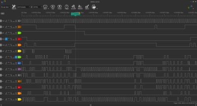
Cap NMI w IRQ zoom.png [ 44.16 KiB | Viewed 3522 times ]
The capture shows that /NMI goes low while an IRQ is in progress, and it stays low even after the interrupt is cleared and /IRQ returns high. In fact, /NMI never goes high again. The three write cycles of the BRK sequence for the IRQ are clearly evident from R/W, but there is no sign of the NMI being serviced. It sure looks like the NMI interrupt is lost.

Sure enough, a look at the TTL CPU’s internal logic confirms that an NMI will be ignored if it arrives after the fetch of the interrupt vector low-byte, but before the end of the SYNC cycle at the end of the BRK sequence. This is exactly the time at which the NMI happens to arrive in the capture above. In fact, the chances of an NMI hitting this vulnerable window are enhanced in this case by the action of RDY (shown on the capture beginning at the cursor). It happens to go low to pause the CPU exactly during the critical SYNC cycle, extending the window of vulnerability over many cycles. :evil:

Ok, so what to do. Obviously we need to close the window, but this raises the obvious question: how does the NMOS 6502 react to overlapping IRQ and NMI events? Dieter shared with me some fascinating info on visual6502.org in that regard. In particular, three points stand out:

  1. A “late” NMI, one which arrives after the BRK sequence has begun but before the interrupt vector low-byte has been fetched, hijacks the IRQ. In this case, the NMI vector is followed, and the IRQ will execute after the NMI is completed.
  2. A “later” NMI, one which arrives after the fetch of the vector low-byte but before the ISR has started, will interrupt the second instruction of the ISR.
  3. A “lost” NMI, one which arrives less than a 1/2 cycle before the fetch of the vector low-byte, is ignored and the NMI is lost.

The TTL CPU already reproduces #1 above — an NMI arriving before the fetch of the vector low-byte will hijack an IRQ already in progress. That’s great, but unfortunately, the other two behaviours are not correct. The problem is that the TTL CPU clears the internal flags for all pending interrupts at the end of the BRK sequence. Admittedly, that’s a bit of a blunt instrument, but pretty much ok for /IRQ and /RES. Both these signals are level-sensitive and will simply be captured once again as soon as the BRK sequence completes.

Of course that’s not true for NMI, which is edge-sensitive. In that case, the pending interrupt flag must not be cleared unless the NMI interrupt is actually being serviced. Now, we know NMI will hijack the interrupt if it arrives before the vector low-byte fetch, so we can be sure we are indeed clearing only a serviced NMI if the flags are cleared immediately after the low-byte fetch (i.e. upon the fall of PHI2 in that cycle). The internal pending-interrupt flags are used only to generate the correct vector low-byte address, so we don’t really need them once that job is done. The fix therefore should not break anything, so far as I can tell, and deal with the problem.

But even with that, a small window still remains while the internal flags are actually being cleared. A low-going ~15ns pulse is used to clear the internal flip-flops, and an NMI will be lost if it is received exactly within that 15ns window. Now this is no worse than the NMOS 6502, which reportedly loses NMIs that land within a 1/2 cycle of the vector low-byte fetch. Just to confirm, I left the IK+ game running in the opening animation sequence for an extended period — something I had not done to this point. If in fact the 6510 in the C64 loses NMI interrupts, then it should be only a matter of time before it too hangs, right?

Well, lo and behold, yes — indeed the game hangs after a few minutes with NMI stuck low. I repeated the tests several times just to be sure, with the same result every time. Wow, turns out the bug was always there! :shock: It’s just that the TTL CPU’s longer vulnerability window makes it more likely to occur. Man o’ man, I would not have guessed that! (Strangely enough, the problem does not seem to resurface during game play, which looks very much like the opening animation. This might also just be only a mater of time, however.)

So, now, with this change, the behaviour of the TTL CPU in this respect should match the 6510 with only two exceptions:
  1. the “Lost NMI” window is 15ns after the vector low-byte fetch, rather than a 1/2 cycle before it; and
  2. a “Later NMI” will interrupt the first instruction of the ISR that follows it, rather than the second.
At this stage, I can only hope that both these incompatibilities will turn out to be benign ... (Yes, hope springs eternal :)).

Alright, so the next step is to look for yet another patch to the existing boards to try to fix this problem. In the meantime, I would appreciate a sanity test here. The specifics of 6502 interrupt handling are a bit tricky, to say the least, and it would not surprise me to learn that I’ve botched this up. Does the behavior described above seem correct? Is it the same on the 65C02? Many thanks in advance for any comments.

Cheers for now,
Drass

_________________
C74-6502 Website: https://c74project.com


Top
 Profile  
Reply with quote  
 Post subject: Re: TTL 6502 Here I come
PostPosted: Sat Nov 03, 2018 9:11 pm 
Offline
User avatar

Joined: Thu Dec 11, 2008 1:28 pm
Posts: 10800
Location: England
> Now this is no worse than the NMOS 6502, which reportedly loses NMIs that land within a 1/2 cycle of the vector low-byte fetch...

Checking the wiki page on this subject, it looks like an NMI would only be lost if it's a short pulse. In the usual 6502 system design, NMI would remain low until the interrupting device is serviced - it doesn't get lost, but it is deferred for a few cycles while the IRQ is taken.

Wiki:
http://visual6502.org/wiki/index.php?ti ... t_Handling

Simulation with short NMI pulse (from that page):
http://visual6502.org/JSSim/expert.html ... =0014&d=78

Simulation with extended NMI pulse (just adjusted one parameter):
http://visual6502.org/JSSim/expert.html ... =0014&d=78


Top
 Profile  
Reply with quote  
 Post subject: Re: TTL 6502 Here I come
PostPosted: Sun Nov 04, 2018 1:53 pm 
Offline
User avatar

Joined: Sun Oct 18, 2015 11:02 pm
Posts: 428
Location: Toronto, ON
Thanks for the clarification BigEd. That’s so interesting!

Reading the Wiki carefully, it seems that in order for the NMI to be lost, it must be a pulse shorter than 2.5 cycles AND arrive within a 1/2 cycle before the low-byte fetch. That suggests NMI is sampled on the rise of PHI2, and sampling is inhibited during the two-cycle vector fetch. A “later” NMI which persists just misses the start of the SYNC cycle that follows, and then interrupts the *second* instruction of the ISR. Excellent.

Unfortunately, replicating this requires more logic than I have on the board. But I think I can get away with sampling on the fall of PHI2 and inhibiting sampling only while the internal interrupt-pending flags are being reset. If NMI goes low during that time, the transition will be picked up once sampling resumes. That should close the window entirely, and have the TTL CPU respond to any NMI pulse across the fall of PHI2 (minus a nominal setup time). It yields different interrupt latency, but the hope is it won’t matter.

Of course, I am now wondering what’s behind the IK+ crash with the 6510 installed? Certainly NMI stays low for more than 2.5 cycles, so perhaps there is some other gremlin in the works. It would be quite something if the fix addresses the lost NMI, and the TTL CPU then replicates the remaining IK+ crash. :shock: Can’t wait to find out.

Ok, time to make the patch and see what happens!

_________________
C74-6502 Website: https://c74project.com


Top
 Profile  
Reply with quote  
Display posts from previous:  Sort by  
Post new topic Reply to topic  [ 558 posts ]  Go to page Previous  1 ... 29, 30, 31, 32, 33, 34, 35 ... 38  Next

All times are UTC


Who is online

Users browsing this forum: No registered users and 6 guests


You cannot post new topics in this forum
You cannot reply to topics in this forum
You cannot edit your posts in this forum
You cannot delete your posts in this forum
You cannot post attachments in this forum

Search for:
Jump to: