6502.org Forum  Projects  Code  Documents  Tools  Forum
It is currently Fri Sep 20, 2024 8:33 pm

All times are UTC


Post new topic Reply to topic  [ 9 posts ] 
Author Message
 Post subject: Bus Monitor PCB
PostPosted: Tue Oct 20, 2015 12:41 pm 
Offline
User avatar

Joined: Sun Sep 08, 2013 10:24 am
Posts: 740
Location: A missile silo somewhere under southern England
The next version of Bus Monitor has arrived! I've created an RS232/command based one, spun it up in Eagle and had it manufactured.
Just got it back and spotted one issue (although not a show stopper): I'll need to run a mod wire from one of the chip GND pins as I forgot to link that part of the ground plane to the rest.

Abilities so far:

16 pins for 6502 address bus input.
8 pins for 6592 data bus input.
7 pins for signals input (active low, unless designated otherwise). Names settable through command line.
1 clock output capable of running in manual mode (push button), 1 Hz, 2Hz, 3Hz, 4Hz and 5Hz (not MHz) for diag. Mode settable via command line.
Set RS232 baud speed, safemode of 9600 in case of errors (hold down clock button during power up)
Load/Save profile information from/to EEPROM (signal names, etc.)

Following commands support:

CLS / CLEAR - clear screen
SHOW / SH - show data form buses/signals
CLOCK - set clock speed/conditon (HIGH, LOW, 1-5Hz). If set HIGH or LOW then clock button sneds 1uS pulse low or high.
RESET - reset the microcontroller
FORMAT / FORM - format the EEPROM for storing profiles
LS / DIR - list profiles stored in EEPROM
DELETE / DEL - delete a profile from EEPROM
SAVE / SA - save a profile to EEPROM
LOAD / LO- load a profile from EEPROM
COLOUR / COL - change the text colour
COM - change the comm speed settings

Most commands are complete, but I need to work on the SHOW command as this is what disapls the input from the various buses. I also need to implement a SIG command to set signal names.

This is my very first PCB design so I hope it works when I solder the on components :mrgreen:.

Pics:
Attachment:
File comment: Top side of PCB
BusMonitor_Topside.jpg
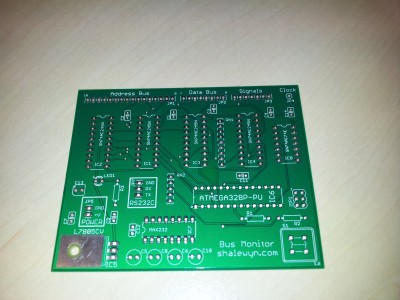
BusMonitor_Topside.jpg [ 2.71 MiB | Viewed 902 times ]

Attachment:
File comment: Underside of PCB
BusMonitor_Underside.jpg
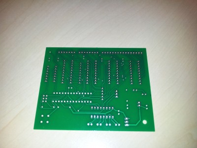
BusMonitor_Underside.jpg [ 2.34 MiB | Viewed 902 times ]


Top
 Profile  
Reply with quote  
 Post subject: Re: Bus Monitor PCB
PostPosted: Tue Oct 20, 2015 12:54 pm 
Offline

Joined: Wed Jan 08, 2014 3:31 pm
Posts: 578
Neat, what sort of applications do you intend to use it for? Tracing of a 6502 as it boots?


Top
 Profile  
Reply with quote  
 Post subject: Re: Bus Monitor PCB
PostPosted: Tue Oct 20, 2015 1:22 pm 
Offline

Joined: Mon Mar 25, 2013 9:26 pm
Posts: 183
Location: Germany
Can you please add the schematic for the pcb?

Mario.

_________________
How should I know what I think, until I hear what I've said.


Top
 Profile  
Reply with quote  
 Post subject: Re: Bus Monitor PCB
PostPosted: Tue Oct 20, 2015 4:50 pm 
Offline
User avatar

Joined: Sun Sep 08, 2013 10:24 am
Posts: 740
Location: A missile silo somewhere under southern England
It's main use is exactly that: when you've just built/prototyped a 6502 system this can be used to step through one cycle at a time and see what's on the buses and what the signals are doing.
I had a it made as I also wanted to see if I could design and have a board manufactured - I've designed proto-types, but never had one created as a PCB.

With regard to the schematic: please see attached.
I'll also be posting the firmware source code when it's finished. Basically, I'm making this open source for anyone to use.

Attachment:
bus_monitor_v2b.jpg
bus_monitor_v2b.jpg [ 1.08 MiB | Viewed 885 times ]


Top
 Profile  
Reply with quote  
 Post subject: Re: Bus Monitor PCB
PostPosted: Tue Oct 20, 2015 6:03 pm 
Offline

Joined: Mon Mar 25, 2013 9:26 pm
Posts: 183
Location: Germany
Seems that your're using the 74AC245 only in one direction. Why not connecting the "dir" pin of all to one pin of the ATMEGA too? You could then read and write to the bus. But a cool project and rather complex for the first pcb.
Hope everything works as expected.

What tool did you used for the pcb? It looks bigger then half an euro board, so Eagle is out, as long as you don't have a licensed version.

Mario.

_________________
How should I know what I think, until I hear what I've said.


Top
 Profile  
Reply with quote  
 Post subject: Re: Bus Monitor PCB
PostPosted: Tue Oct 20, 2015 8:53 pm 
Offline
User avatar

Joined: Sun Sep 08, 2013 10:24 am
Posts: 740
Location: A missile silo somewhere under southern England
I really wanted to keep things passive for now given that this is my first proper PCB project. In future I'll see if I can do a more bus interactive one.

By the way, I did create this in Eagle free edition, using the maximum size allowed and double sided only. In future I might try to create something in Kicad as I sure as heck cannot afford an Eagle license (at least not the pro version).

Here's a few more pics of it soldered and actually working (just finished trying to clean the flipping flux off :roll:). Oh, and I did need to put in a link for the one of the buffer IC GND pins. Apparently it's quite normal to have one or two issues with a new board?

Top side:

Attachment:
busmon_topside.JPG
busmon_topside.JPG [ 3.03 MiB | Viewed 862 times ]


Underside:

Attachment:
busmon_underside.JPG
busmon_underside.JPG [ 3.3 MiB | Viewed 862 times ]


Plugged in (power + RS232 + ISP programmer):

Attachment:
busmon_pluggedin.JPG
busmon_pluggedin.JPG [ 3.02 MiB | Viewed 862 times ]


PuTTY display via RS232:

Attachment:
busmon_display.jpg
busmon_display.jpg [ 45.72 KiB | Viewed 862 times ]


Top
 Profile  
Reply with quote  
 Post subject: Re: Bus Monitor PCB
PostPosted: Tue Oct 20, 2015 10:23 pm 
Offline
User avatar

Joined: Sun Sep 08, 2013 10:24 am
Posts: 740
Location: A missile silo somewhere under southern England
I'm probably going to implement a menu command which will both show the bus and signal info and allow changing the clock speed at the same time.
Next stage: test using one of my 6502 projects! :)


Top
 Profile  
Reply with quote  
 Post subject: Re: Bus Monitor PCB
PostPosted: Wed Oct 21, 2015 8:39 am 
Offline

Joined: Mon Mar 25, 2013 9:26 pm
Posts: 183
Location: Germany
Nice job and it works. Having minor issues with the first version of a board is not unusual. You're running the ATMEGA with the internal 8MHz oscillator?
I like the Arduino Nano for such a job. You can get a clone for $3, it is really small and provides an USB Serial interface. So no need for a MAX232. And it runs on a true 16MHz clock.

I think I will try to create a similar board for testing and driving 8bit processors.

Mario.

_________________
How should I know what I think, until I hear what I've said.


Top
 Profile  
Reply with quote  
 Post subject: Re: Bus Monitor PCB
PostPosted: Wed Oct 21, 2015 9:38 pm 
Offline
User avatar

Joined: Sun Sep 08, 2013 10:24 am
Posts: 740
Location: A missile silo somewhere under southern England
Yep, I'm using the internal 8MHz oscillator. To be honest, I don't think you need 16MHz for this. In fact, 8 MHz is also OTT as well.
However, using an arduino nano is a good idea. I chose to go the 'naked' AVR route as I wanted an excuse to design and build my own board. All down to personal choice :).

With regard to writing back to the buses; What do you hope to achieve by doing this? I.e. do you want to simulate a ROM, RAM or otehr such device?


Top
 Profile  
Reply with quote  
Display posts from previous:  Sort by  
Post new topic Reply to topic  [ 9 posts ] 

All times are UTC


Who is online

Users browsing this forum: GARTHWILSON and 46 guests


You cannot post new topics in this forum
You cannot reply to topics in this forum
You cannot edit your posts in this forum
You cannot delete your posts in this forum
You cannot post attachments in this forum

Search for:
Jump to: