6502.org Forum  Projects  Code  Documents  Tools  Forum
It is currently Sat May 04, 2024 7:41 pm

All times are UTC


Post new topic Reply to topic  [ 733 posts ]  Go to page Previous  1, 2, 3, 4, 5, 6 ... 49  Next
Author Message
PostPosted: Sun Jun 21, 2015 3:25 pm 
Offline
User avatar

Joined: Sun Oct 13, 2013 2:58 pm
Posts: 485
Location: Switzerland
Quote:
This is also why I can't see the reason to use EEPROM in a 65C02 project these days when for a few cents, you can pre-load a fast SRAM and do away with all the wonky propagation issues and slow clocks needed to support 150ns technology, not to mention having to dredge up an expensive programmer.


That's exactly what I think is the easiest way for a fast system. I had my share with slow (90ns) EEPROMs and the problem when setting up a system the first time, especially the iteration of pulling the EEPROM, putting it into the programmer and then back. Only to find out that you only found the second last error in your monitor.

It's impressive to see the fast progress you make even with the rules you have put onto yourself and the type of circuits you're using, and how neatly you are laying out your cables. When I do my breadboard projects they are first not half the size of your MoBB, the maximum I use is 5 units and you have this 18-unit monster. I also like the trick adding intermediate latches to avoid problems with the propagation delay with many stages of signal processing. It's almost like a modern CPU with pipelines.

Hope to see the first real video output.

One question I have, when you talk about GPU I suppose it is more a CRTC for VGA signals as you do all video data calculation in the CPU? Is that correct?

cheers

Peter


Top
 Profile  
Reply with quote  
PostPosted: Mon Jun 22, 2015 1:20 am 
Offline
User avatar

Joined: Mon May 25, 2015 2:25 pm
Posts: 632
Location: Gillies, Ontario, Canada
The damn black-flies were insane out in the back 40, so I came in for a quick wiring break.

Image
Added 9 bit bus wiring from the X and Y counters to the Horizontal and Vertical comparators.

Image
There are 10 x 8 bit comparators, so I cut 80 small wires. Go ahead, count em!

Image
Each comparator is an 8 input AND gate. All input wires attached.

The top row of comparators are responsible for trigger the following events...

1) Horizontal Sync Pulse On
2) Horizontal Sync Pulse Off
3) Horizontal Blanking On
4) Horizontal Blanking Off
5) Horizontal Line Reset

The lower row of comparators are responsible for trigger the following events...

1) Vertical Sync Pulse On
2) Vertical Sync Pulse Off
3) Vertical Blanking On
4) Vertical Blanking Off
5) Vertical Line Reset

Each On and Off sequence triggers a Set or Reset on a 74HC74 Flip-flop.

Timings are based on the 40Mhz, 800x600, 60Hz VGA standard, divided in half.

Next photos I show will hopefully have pixels on a screen!

Cheers,
Radical Brad


Last edited by Oneironaut on Tue Jun 23, 2015 7:35 pm, edited 1 time in total.

Top
 Profile  
Reply with quote  
PostPosted: Mon Jun 22, 2015 1:32 am 
Offline
User avatar

Joined: Thu May 28, 2009 9:46 pm
Posts: 8173
Location: Midwestern USA
Oneironaut wrote:
There are 10 x 8 bit comparators, so I cut 80 small wires. Go ahead, count em!

Cutting them isn't the bad part. It's the stripping the ends that would quickly become major tedium. :lol:

_________________
x86?  We ain't got no x86.  We don't NEED no stinking x86!


Top
 Profile  
Reply with quote  
PostPosted: Mon Jun 22, 2015 5:32 am 
Offline
User avatar

Joined: Sun Oct 13, 2013 2:58 pm
Posts: 485
Location: Switzerland
Hi BDD,

stripping the ends is no problem, with the right tool this is done fast. Good ones are not cheap, about 100USD, but they are worth it. It saves you a lot of dentist bills.

cheers

Peter


Top
 Profile  
Reply with quote  
PostPosted: Mon Jun 22, 2015 10:17 am 
Offline
User avatar

Joined: Mon May 25, 2015 2:25 pm
Posts: 632
Location: Gillies, Ontario, Canada
I use a small Swiss Jack-knife. Just roll the end along the blade and pull.
Wires are cut and untwisted from Cat5 cable.

Brad


Top
 Profile  
Reply with quote  
PostPosted: Mon Jun 22, 2015 4:12 pm 
Offline
User avatar

Joined: Mon May 25, 2015 2:25 pm
Posts: 632
Location: Gillies, Ontario, Canada
As I look through the great list of DIY 6502 projects on this site, I realize that there are actually no Game Systems.

Perhaps Vulcan-74 could be the first in a new category "Game Systems"?
My only user interface will be a cartridge port (serial EEPROM), and a dual joystick port, C64 style, of course!

Of course, this is after I finish the writeup, schematics and prove that this beast will actually work!

Brad


Top
 Profile  
Reply with quote  
PostPosted: Mon Jun 22, 2015 7:21 pm 
Offline
User avatar

Joined: Sun Oct 13, 2013 2:58 pm
Posts: 485
Location: Switzerland
Quote:
The top row of comparators are responsible for trigger the following events...

1) Horizontal Sync Pulse On
2) Horizontal Sync Pulse Off
3) Horizontal Blanking On
4) Horizontal Blanking Off
5) Horizontal Line Reset

The lower row of comparators are responsible for trigger the following events...

1) Vertical Sync Pulse On
2) Vertical Sync Pulse Off
3) Vertical Blanking On
4) Vertical Blanking Off
5) Vertical Line Reset

Each On and Off sequence triggers a Set or Reset on a 74HC74 Flip-flop.


And in addition this requires more than 180 connections plus space and decoupling condensators for the 74HC688 plus the 74HC74 flip-flops. You should definitively consider GALs for that task. It's much easier. I would say two GAL16V8 would be more than enough. If you want that system to be the future "Game System" it has to be easier to implement. Ok, you could sell "building your own computer as 1000+ piece puzzle" as the introductory "game" :wink:


Top
 Profile  
Reply with quote  
PostPosted: Mon Jun 22, 2015 7:36 pm 
Offline
User avatar

Joined: Mon May 25, 2015 2:25 pm
Posts: 632
Location: Gillies, Ontario, Canada
Indeed, it's almost insane how many wires and ICs I am going to use in this project!

But to be honest, I am not looking for an easy way. This is about using as many 7400 chips as I need to meet or exceed my original goals.
The more difficult this project becomes, the more fun I will have.

This is why I coined the project Vulcan-74, because it's almost pure logic.

I have done many single FPGA / CPLD / Microcontroller systems in the past, and they were fun.
This time I want my face planted deep into the bare metal!

Originally, I was intending to make my own gate logic CPU for this beast, but decided to start with my favorite processor first.

Here are some of my single chip Game Systems made over the last 10 years...


Image
https://www.youtube.com/watch?v=CXFOTpM2Jn4
Single XMega over clocked to 60Mhz to bit-bang color NTSC!


Image
https://www.youtube.com/watch?v=IRroMaaCAn4
FPGA with external SRAM clocked at 80MHz.


Image
https://www.youtube.com/watch?v=yr66L9WytIY
Matrix rain on a single FPGA.


And my favorite "impossible" single chip design using nothing but an ATTiny...

Image
https://www.youtube.com/watch?v=8Z5Gcl8Py7Y
Only 512 bytes of memory and 4 IO pins!!!


I have dozens of other systems that are mainly code and a few ICs, but this time I want to do it mostly in hardware.
The GPU section of Vulcan-74 will probably be my pinnacle creation.... if it works as planned!

So the short response... I ain't lookin' for no easy way, dude!
But thanks for the input, this is a great community!!

Cheers,
Brad


Top
 Profile  
Reply with quote  
PostPosted: Mon Jun 22, 2015 8:22 pm 
Offline
User avatar

Joined: Sun Oct 13, 2013 2:58 pm
Posts: 485
Location: Switzerland
Ahh, your favorite is really nice, I like it.


Top
 Profile  
Reply with quote  
PostPosted: Mon Jun 22, 2015 8:41 pm 
Offline
User avatar

Joined: Mon May 25, 2015 2:25 pm
Posts: 632
Location: Gillies, Ontario, Canada
Thanks!

It was fun to push that chip beyond the fabric of reality.
Used every byte of SRAM, overclocked 160%, all interrupts used, and even tricked one of the IO pins.

The XMega was actually fun as well, with amazing overclocking ability up to 70MHz.
I actually found that an overclocked XMega would easily outperform LPC-ARM for IO speed.

But so far, no other project generates the excitement that this one has.
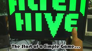
Seeing the monitor lock on to a perfect 800x600 screen and display video from a mess of logic chips on a breadboard is amazing!
I must have done 10 revisions (from scratch) to finally get it perfect, but it has been fun.

You would think that just getting 120,000 pixels out to a screen at 60 frames per second would be challenging, but the most difficult part has been the first and last pixel. In order to have the first and last pixel the same width as other pixels, all signals must converge precisely at the same time - h-blank, v-blank, addressing, data output, and horizontal sync. Fall off by even 2ns, and you get horrible banding and pixel clock issues on an LCD.

When I redid the design the last time, I added 74HC574 registers every 36ns or so on all video signals, syncing them with the clock.
I learned this while doing FPGA projects to make video... clock buffers and added register levels!

Making a game system is fun hobby - It's like watching TV, but instead the viewer does the programming!

Brad


cbscpe wrote:
Ahh, your favorite is really nice, I like it.


Top
 Profile  
Reply with quote  
PostPosted: Tue Jun 23, 2015 4:08 pm 
Offline
User avatar

Joined: Mon May 25, 2015 2:25 pm
Posts: 632
Location: Gillies, Ontario, Canada
Here is a snapshot of the last segment of the video driver responsible for synced output and blanking.
The use of the dual AND gates keep propagation under my set limit.
Originally, I used 74HC157 data selectors, but they had a 20ns throughput.

One might ask... "why not just use the last 573 OE as a blanking control"?
... there is a reason!


Image

Brad


Top
 Profile  
Reply with quote  
PostPosted: Tue Jun 23, 2015 4:46 pm 
Offline
User avatar

Joined: Fri Dec 11, 2009 3:50 pm
Posts: 3351
Location: Ontario, Canada
Oneironaut wrote:
One might ask... "why not just use the last 573 OE as a blanking control"?
... there is a reason!
Two reasons I can think of. Replacing the 'hc574 with an 'hc273 would solve one of them...

Love what you're doing, btw!

J. :)

_________________
In 1988 my 65C02 got six new registers and 44 new full-speed instructions!
https://laughtonelectronics.com/Arcana/ ... mmary.html


Top
 Profile  
Reply with quote  
PostPosted: Tue Jun 23, 2015 5:00 pm 
Offline
User avatar

Joined: Sun Jun 30, 2013 10:26 pm
Posts: 1928
Location: Sacramento, CA, USA
Oneironaut wrote:
Here is a snapshot of the last segment of the video driver responsible for synced output and blanking...

Your latest .jpg (http://lucidscience.com/temp/vsch1.jpg) doesn't show in my browser, Brad.

Mike B.

[Edit: Oh, now it does. I don't know if the temporary problem was at my end or yours, but it's fine now.]


Top
 Profile  
Reply with quote  
PostPosted: Tue Jun 23, 2015 5:21 pm 
Offline
User avatar

Joined: Mon May 25, 2015 2:25 pm
Posts: 632
Location: Gillies, Ontario, Canada
Thanks for the positive feedback!

Close on the 273, but it would suffer the same issue as the OE on the 574. Of course, with the 273, you wouldn't have to use pull-down resistors to hold the low level required during blanking, but alas, there would be another problem.

So far I have tried using 273, 373, 245, 157, and several other combinations until I found this one, which works perfectly for 400x300 or 640x480 speeds.

Anyone care to venture a guess as to what issue this odd circuit solves?
I bent my brain for many nights until I came up with the 74HC08 solution!

Brad

Dr Jefyll wrote:
Oneironaut wrote:
One might ask... "why not just use the last 573 OE as a blanking control"?
... there is a reason!
Two reasons I can think of. Replacing the 'hc574 with an 'hc273 would solve one of them...

Love what you're doing, btw!

J. :)


Top
 Profile  
Reply with quote  
PostPosted: Tue Jun 23, 2015 6:07 pm 
Offline
User avatar

Joined: Fri Dec 11, 2009 3:50 pm
Posts: 3351
Location: Ontario, Canada
Quote:
you wouldn't have to use pull-down resistors to hold the low level required during blanking, but alas, there would be another problem.
Right -- that's one of the problems I noticed. The other is that, on '574 (or '273), the prop delay from clock to output will differ from the prop delay from OE\ (or CLR\) to output. To provide the absolute timing regularity that video demands, it's pretty well obligatory to arrange things so a single clock signal updates both pixel data and blanking.

I would consider replacing the '574 with a pair of '163 counters, which offer synchronous load and synchronous clear, both from a single clock. (Load and clear are the only functions you require -- no counting is involved.) And you can eliminate the AND gates from your circuit.

'163s are great little chips -- good for so much more than just counting!

cheers,
Jeff


Attachments:
74AC163, 74ACT163.pdf [112.09 KiB]
Downloaded 147 times

_________________
In 1988 my 65C02 got six new registers and 44 new full-speed instructions!
https://laughtonelectronics.com/Arcana/ ... mmary.html


Last edited by Dr Jefyll on Tue Jun 23, 2015 6:19 pm, edited 1 time in total.
Top
 Profile  
Reply with quote  
Display posts from previous:  Sort by  
Post new topic Reply to topic  [ 733 posts ]  Go to page Previous  1, 2, 3, 4, 5, 6 ... 49  Next

All times are UTC


Who is online

Users browsing this forum: Google [Bot] and 10 guests


You cannot post new topics in this forum
You cannot reply to topics in this forum
You cannot edit your posts in this forum
You cannot delete your posts in this forum
You cannot post attachments in this forum

Search for:
Jump to: