6502.org Forum  Projects  Code  Documents  Tools  Forum
It is currently Sun Apr 28, 2024 9:14 pm

All times are UTC


Post new topic Reply to topic  [ 20 posts ]  Go to page 1, 2  Next
Author Message
 Post subject: Voltage drops on my SBC
PostPosted: Tue Sep 09, 2014 9:09 pm 
Offline

Joined: Mon Aug 05, 2013 10:43 pm
Posts: 258
Location: Southampton, UK
This is not a 6502, or even a microprocessor-related question, so if you want to ask me to go elsewhere to find these answers then go ahead. However, the wealth of knowledge around these parts is impossible to resist. :)

Anyway, my computer is working very well (beside this specific problem) and has many ICs:

:arrow: MPU (I won't say which one) ;) (36mA)
:arrow: AS6C4008 SRAM (30mA)
:arrow: AT28C256 EEPROM (50mA)
:arrow: XP88C681 DUART (15mA)
:arrow: XC95108 CPLD (not quite full) (~~100mA)
:arrow: 65C22 VIA (don't know - 30mA?)
:arrow: GI-8912 FM Synth (80mA)
:arrow: XC9572 CPLD (65SPI) (~70mA)
:arrow: DS3234 RTC + temp (~0A)
:arrow: V9958 VDC (230mA!)
:arrow: 6 x D51464 DRAMs (attached to VDC) (datahsheet says 75mA *each*?)

So rather a lot of ICs, and a few in high-current NMOS. Ignoring the DRAMs, this makes 641mA, which is very close to what I see with the meter (700mA). Those old NMOS parts sure take a lot of current, but then so do the comparatively modern XC5xx parts. This would not normally be a problem; I'm powering the boards (there are two stacked together) from an ATX powersupply rated at 5V/19A.

However, I do not understand why I see large voltage drops on many/most of the ICs. The voltage drop is so bad that if I socket the GI-8912 it does not start. Measuring the voltage on some key ICs shows only about 4.4V, which explains why the computer does not function.

Can someone explain to me what the problem(s) might be and how I might overcome this issue? I thought I had a reasonable grasp of electronics, but this comparatively simple problem has stumped me. It is hard to figure out where the voltage is "going missing" since I can measure the resistance from opposite "corners" and I get a 0 Ohm reading on the meter, yet if I measure the voltage at the power connector I see no drop. The PCBs are 2 layer with fairly liberal sized power tracks going around the perimeter, and with some redundancy going across the board as well. Would a 4 layer board with dedicated power layers help? All ICs are decoupled. I can supply schematics and PCB designs if anyone is interested.

Thanks for any and all insight!

_________________
8 bit fun and games: https://www.aslak.net/


Top
 Profile  
Reply with quote  
PostPosted: Wed Sep 10, 2014 1:47 am 
Offline
User avatar

Joined: Sun Jun 30, 2013 10:26 pm
Posts: 1927
Location: Sacramento, CA, USA
Hmm ... Ohm's Law should be your friend here, but sometimes things can creep in and cause theory and practice to diverge. I have found (static) resistance measurements to be of limited value in practice (I work in the automotive field), because flaky connections can change resistance rather dynamically under different loads, temperatures, humidities, and other conditions. Your voltage-drop technique should be sufficient to isolate the problem, assuming that you have access to enough measuring points to get an idea of what's going on. I suspect that it could be something as simple as a cold solder joint (or its equivalent if you're not using solder), but that's pure conjecture on my part.

One possible strategy would be to run external temporary shunt wires to key areas while monitoring the voltage drop, and see where that takes you.

I wish you the very best.

Mike


Top
 Profile  
Reply with quote  
PostPosted: Wed Sep 10, 2014 2:52 am 
Offline
User avatar

Joined: Fri Aug 30, 2002 1:09 am
Posts: 8428
Location: Southern California
In the 1970's everything took a lot of power yet we did not have multilayer boards, so I don't think that's the problem here.

_________________
http://WilsonMinesCo.com/ lots of 6502 resources
The "second front page" is http://wilsonminesco.com/links.html .
What's an additional VIA among friends, anyhow?


Top
 Profile  
Reply with quote  
PostPosted: Wed Sep 10, 2014 4:19 am 
Offline
User avatar

Joined: Fri Dec 11, 2009 3:50 pm
Posts: 3349
Location: Ontario, Canada
Aslak3 wrote:
However, I do not understand why I see large voltage drops on many/most of the ICs. The voltage drop is so bad that if I socket the GI-8912 it does not start.
It's highly plausible there's another reason (other than current consumption) why socketing the GI-8912 stops the show. But in any case your best strategy is to begin by fixing the voltage drop, then deal with the GI-8912 later.

Are we to assume that this is a newly-built project? If you've accidentally omitted a trace or two, it's possible you have some chips actually lacking a connection to Gnd, or lacking a connection to +5 :!: Although you might assume that'd result in a voltage reading of zero across the chip's supply pins, you'd be mistaken, since chips lacking a supply connection can sap power from their input signals instead -- a sort of back-flow, which I won't bother to explain properly. (Maybe if you'd chosen a 65xx cpu I would!) :wink:

Mike mentioned access points, and that's the key -- checking the voltage at multiple places so you can identify the location of the problem. There are two paths you need to verify -- ground and supply ( 0 volt and +5 volt). So, here's one possible way to proceed...

  • measure the voltage from 0 at the power supply (PSU) to +5 at the power supply. Supposed to read 5 volts.

  • next, measure from Gnd at the PSU to +5 on one of the chips on the board. In theory this should read the same (5 volts), since in theory there's a good connection from +5 to +5, and measuring one end of a good connection is the same as measuring the other end. If they're not the same it isn't a good connection. :!: In that case, trace step by step along the +5 connection chain (that connects the PSU to the chip) until you see where the drop is. Of course the other voltmeter probe remains on 0 at the PSU.

  • If that seach is fruitless, do the same thing "upside down." Measure from +5 at the PSU to 0 on one of the chips on the board. In theory there's a good connection from 0 to 0, so you should read the same 5 volts. If not, trace step by step along the 0 volt connection chain (that connects the PSU to the chip) until you see where the drop is. The other voltmeter probe remains on +5 at the PSU.

Be aware you may see a slight voltage drop here and there, which perhaps is tolerable, but probably there's a single major fault causing most of the trouble. Good luck, & HTH...

cheers,
Jeff

_________________
In 1988 my 65C02 got six new registers and 44 new full-speed instructions!
https://laughtonelectronics.com/Arcana/ ... mmary.html


Top
 Profile  
Reply with quote  
PostPosted: Wed Sep 10, 2014 5:32 am 
Offline
User avatar

Joined: Thu May 28, 2009 9:46 pm
Posts: 8152
Location: Midwestern USA
Dr Jefyll wrote:
Mike mentioned access points, and that's the key -- checking the voltage at multiple places so you can identify the location of the problem. There are two paths you need to verify -- ground and supply ( 0 volt and +5 volt). So, here's one possible way to proceed...

Same advice I was about to give. :lol:

One other thing: You didn't mention if all of the chips are socketed. You may simply be a victim of junky sockets. I've certainly run into enough of those over the years.

_________________
x86?  We ain't got no x86.  We don't NEED no stinking x86!


Top
 Profile  
Reply with quote  
PostPosted: Wed Sep 10, 2014 5:45 am 
Offline

Joined: Sat Jul 28, 2012 11:41 am
Posts: 442
Location: Wiesbaden, Germany
Do you have a filter capacitor (usually 100nF) as close as possible to each ICs power inputs?

Due to state switching of digital ICs a high frequency current surge on the power pins can cause the voltage to drop as the power traces on the PCB act as an inductance. A larger electrolytic capacitor (some µF) should support the power of the whole PCB at the power input to the PCB.

_________________
6502 sources on GitHub: https://github.com/Klaus2m5


Top
 Profile  
Reply with quote  
PostPosted: Wed Sep 10, 2014 6:08 am 
Offline
User avatar

Joined: Fri Dec 11, 2009 3:50 pm
Posts: 3349
Location: Ontario, Canada
Good point about the capacitors.

Likewise the point about the IC sockets -- that's one link in the chain of connections I mentioned. And probably there are other plug/socket locations -- for example, the connector on the board, from the wire bringing power from the PSU.

Incidentally, the wire itself will produce a voltage drop, which may be excessive if the wire to the PSU is too thin and/or too long. I made that mistake myself once back in the 80's, and had to switch to a heavier gauge. NMOS. Yeesh!! :roll:

_________________
In 1988 my 65C02 got six new registers and 44 new full-speed instructions!
https://laughtonelectronics.com/Arcana/ ... mmary.html


Top
 Profile  
Reply with quote  
PostPosted: Wed Sep 10, 2014 11:55 am 
Offline

Joined: Mon Aug 05, 2013 10:43 pm
Posts: 258
Location: Southampton, UK
Thanks so much for the tips and suggestions!

I am not accustomed to Ohm's law not being helpful with these kinds of problems, but then I am not exactly "seasoned" and have only made trivial circuits up before this, my largest project to date.

The boards are professionally made up, and designed by me. All ICs are socketed. I debated about socketing the DRAMs, but since I wasn't 100% confident the board was going to be my "final" version I still went for sockets for these relatively cheap parts.

I think my strategy will be to measure the voltage across as many ICs as possible, moving along the power rails. Would it make sense to pull all the ICs and replace them one at a time, measuring for drops as I go? That might be iluminating. I can work on the main computer board first (MPU, EEPROM, SRAM, DUART, CPLD) because it shows the problem as well, albeit not bad enough to prevent the computer running.

Here is a picture of the main board PCB to give some context:

Attachment:
6809computercpld.png
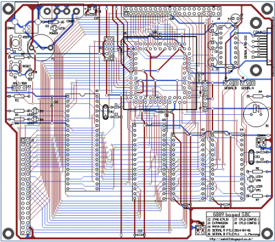
6809computercpld.png [ 252.83 KiB | Viewed 1415 times ]


The round part south of the Molex at the top left is a vertical fuse holder, incase anyone was wondering.

The design constraints (10mil DRC, only 45degree runs) might be a bit strange and I might not make the next board to the same rules, but I was/am fairly pleased with the use of the space etc. Anyway, you can see the power connectors clearly: A harddisk-style Molex and USB (odd choice, perhaps). Vcc and ground run around the edge. You can see also that there are 3 points used to bridge Vcc and ground onto the "top" IO board (bottom left on the main header, bottom and bottom right). I deliberately wanted to distribute the power rail into multiple places on the IO board.

Some inline replies:

barrym95838 wrote:
One possible strategy would be to run external temporary shunt wires to key areas while monitoring the voltage drop, and see where that takes you.


I think this is an excellent idea. Since I can clearly measure 5V on the Molex, it should be possible to hook this onto the IO board directly at a point where I can see a drop.

GARTHWILSON wrote:
In the 1970's everything took a lot of power yet we did not have multilayer boards, so I don't think that's the problem here.


Yes, this is a source of much comfort. :) I'm inclined to hunt out some of those old PCB designs and see how they did it.

BDD wrote:
One other thing: You didn't mention if all of the chips are socketed. You may simply be a victim of junky sockets. I've certainly run into enough of those over the years.


One thing I don't understand, and please forgive my ignorance, is how a bad socket would cause problems with voltage drops? Could it cause problems on other pins? I am measuring the "elbow" of the pin, and not the voltage at the pad, so I guess it could be that? Hmm!!

Klaus2m5 wrote:
Do you have a filter capacitor (usually 100nF) as close as possible to each ICs power inputs?


I have 100nF caps on all ICs, as close as I could get them. There are only 4 on the main CPLD, which I know isn't /quite/ enough. The board is also decoupled as a whole with 100nF and 100uF caps.

Dr Jefyll wrote:
Incidentally, the wire itself will produce a voltage drop, which may be excessive if the wire to the PSU is too thin and/or too long. I made that mistake myself once back in the 80's, and had to switch to a heavier gauge. NMOS. Yeesh!! :roll:


It's a standard (working well, I believe) ATX powersupply going directly onto a Molex connector. Yes, NMOSs are a hog, but then those CPLDs draw the current, heat up, etc pretty good as well...

Thanks everyone for the tips and advice! I'll be sure to resume my fault-finding efforts this evening...

_________________
8 bit fun and games: https://www.aslak.net/


Top
 Profile  
Reply with quote  
PostPosted: Wed Sep 10, 2014 3:28 pm 
Offline
User avatar

Joined: Fri Dec 11, 2009 3:50 pm
Posts: 3349
Location: Ontario, Canada
Aslak3 wrote:
I am not exactly "seasoned" and have only made trivial circuits up before this, my largest project to date.
Congratulations on your accomplishment, then! This project is not trivial, so obviously you have expanded your scope considerably.

Quote:
Would it make sense to pull all the ICs and replace them one at a time, measuring for drops as I go?
IMO that'd just confuse the issue. Leave the chips in, and just use your voltmeter.

The thing to remember is that good connections don't produce voltage drop. For example, that fuse and its socket are a potential weak link in the chain. If you measure the voltage immediately before and immediately after the fuse socket, do you get the same result? The readings should be virtually identical; otherwise you know the fuse is tarnished or dirty, or not snuggly fitted in the socket. Stuff like that happens all the time.

There's many a slip twixt cup and lip! The female Molex pin from the PSU doesn't attach straight to elbows of the pins on the IC's. There are other links in the chain, and that's the basis for the systematic approach I recommended -- measuring at multiple access points.

All you need to identify the fault location is your voltmeter. Adding shunts is one step removed, IMO -- it'll work, but you'd still need the voltmeter to see whether the shunt has made a difference. So, it becomes a four-handed job rather than two-handed. It's probably best to save the shunt until the very last step -- merely as confirmation that you have narrowed down the exact location of the problem(s).

BTW, can you explain why your Single Board Computer has two boards? :D LOL! But, seriously, I see another weak link, and that's the fact that, on the header from the main board to the expansion, you have only a single pin each for 0 and +5. I suggest next time you use multiple pins for each.

cheers,
Jeff

_________________
In 1988 my 65C02 got six new registers and 44 new full-speed instructions!
https://laughtonelectronics.com/Arcana/ ... mmary.html


Top
 Profile  
Reply with quote  
PostPosted: Wed Sep 10, 2014 7:11 pm 
Offline
User avatar

Joined: Fri Aug 30, 2002 1:09 am
Posts: 8428
Location: Southern California
Dr Jefyll wrote:
For example, that fuse and its socket are a potential weak link in the chain. If you measure the voltage immediately before and immediately after the fuse socket, do you get the same result? The readings should be virtually identical; otherwise you know the fuse is tarnished or dirty, or not snuggly fitted in the socket. Stuff like that happens all the time.

That reminds me of an episode when I was repairing large, semi-professional tape recorders at TEAC in 1982. One day I was working on an 8-channel one using 1/2" tape and 10" reels, with a half-dozen fuses in the power supply. There was a power supply problem but all power supply voltages were present (ie, none dead)-- it's just that one was a tad low and regulation on it was not good, and it was causing strange problems. The symptoms made no sense. It drove me nuts for hours. Fuses are an easy thing to check first, which I did (but not thoroughly enough). None of them were burned or loose, but it turned out that one had let go at one end, under the cap where you couldn't see it through the glass, possibly fatigued from vibration. I would have caught it early if I had actually taken a meter to the fuses instead of just visually confirming that none were blown. The faulty supply line was getting power through protection diodes and other diode junctions that were in the circuit for other purposes. Your 4.4V is 5V minus a silicon diode voltage drop, or minus a couple of Shottky diode drops. Could that have anything to do with it? I can imagine a connector pin not getting soldered for example, or solder being cracked if it doesn't have lead in it.

I have never had trouble with double-wipe soldertail IC sockets. Surprisingly, I have had trouble with the expensive screw-machine sockets, after quite a few IC insertions and extractions.

_________________
http://WilsonMinesCo.com/ lots of 6502 resources
The "second front page" is http://wilsonminesco.com/links.html .
What's an additional VIA among friends, anyhow?


Top
 Profile  
Reply with quote  
PostPosted: Wed Sep 10, 2014 9:28 pm 
Offline

Joined: Mon Aug 05, 2013 10:43 pm
Posts: 258
Location: Southampton, UK
Dr Jefyl wrote:
Congratulations on your accomplishment, then! This project is not trivial, so obviously you have expanded your scope considerably.


Thank you. :) I've been working on this about 18 months now, couple of hours a week on average. Started off with the classic MPU+EEPROM+Glue+Latch+LEDs on breadboard. Nearly bought a tear to my eye when the test pattern played out in front of my eyes. First time applying power too! It's been a very rewarding 18 months I must say.

Quote:
If you measure the voltage immediately before and immediately after the fuse socket, do you get the same result? The readings should be virtually identical; otherwise you know the fuse is tarnished or dirty, or not snuggly fitted in the socket. Stuff like that happens all the time.


You got it exactly! I don't know why I didn't check the fuse. Voltages measured to the Molex ground pins. Measurements are the with the main board powered only:

:arrow: +5V on Molex: 5.12V
:arrow: Near side of fuse: 5.12V
:arrow: Far side of fuse: 4.94V
:arrow: Everywhere else: 4.94V

Hmm! Attaching the IO board yields the 4.4V on the far side of the fuse. More Hmming!

Measuring the resisteance of the fuse (I tried several, all the small form factor 1A type): 1.3 Ohms

Assuming, say 700mA, this will give 0.91V, which is a little more then 5.12-4.4V, but close enough. So, this device I included in my circuit for safety is the cause of all the problems. I'm not sure if I'm using the wrong type of fuse? Out of curiosity I measured the resistance on a household 3A mains fuse and it measured clear 0.

As a very dirty bodge I have simply bridged the fuse on the backside of the board, but would like a 0 Ohm 1A fuse installed, if it is possible to make such a thing. I'm guessing probably not, since a fuse is after all a thin wire....In any case the computer is working just great! Save for the GI 8912 not producing any sounds, but that is a completely different problem.

Quote:
The female Molex pin from the PSU doesn't attach straight to elbows of the pins on the IC's.


You couldn't state that any clearer. :)

Quote:
BTW, can you explain why your Single Board Computer has two boards? :D LOL! But, seriously, I see another weak link, and that's the fact that, on the header from the main board to the expansion, you have only a single pin each for 0 and +5. I suggest next time you use multiple pins for each.


Haha! Yes, a good question. The project started off as just an MPU + DUART style computer, and I really didn't think I'd get even that working in PCB form. But when it all came together I realised there was scope to add the IO board. So basically I called it an SBC because I didn't dare think it might be more. And I know SBCs can have video etc, but that's not a "true" SBC to me; that's a fully featured computer that happens to be on one board. ;)

There are 5 pins at 3 locations routing power between the boards, but yes, there could be more.

In case anyone is interested, here is a picture of the assembled computer:

Attachment:
IMAG0934.jpg
IMAG0934.jpg [ 1.01 MiB | Viewed 1373 times ]


Thanks again for everyones help! I certainly learned a lot about fault finding. :)

_________________
8 bit fun and games: https://www.aslak.net/


Top
 Profile  
Reply with quote  
PostPosted: Wed Sep 10, 2014 9:41 pm 
Offline
User avatar

Joined: Fri Aug 30, 2002 1:09 am
Posts: 8428
Location: Southern California
If fuses didn't have resistance, they wouldn't produce the heat needed to blow when they're supposed to. I haven't studied fuses' details, but I think a lower-voltage fuse is in order. At 250V (a common fuse rating), a 1.3V drop for 1A is piddly. At 5V, it's not; so if you could find one made to be used at lower voltages, you'll do better. I think more typically a regulator is spec'ed to limit the current to a level that's appropriate considering the circuit it's supposed to power, so the output voltage is constant up to that level of current; then no fuse is used after the regulator.

I'm glad you got it going.

_________________
http://WilsonMinesCo.com/ lots of 6502 resources
The "second front page" is http://wilsonminesco.com/links.html .
What's an additional VIA among friends, anyhow?


Top
 Profile  
Reply with quote  
PostPosted: Thu Sep 11, 2014 5:57 am 
Offline
User avatar

Joined: Thu May 28, 2009 9:46 pm
Posts: 8152
Location: Midwestern USA
BTW, what is the width of the power distribution traces?

_________________
x86?  We ain't got no x86.  We don't NEED no stinking x86!


Top
 Profile  
Reply with quote  
PostPosted: Thu Sep 11, 2014 11:06 am 
Offline

Joined: Mon Aug 05, 2013 10:43 pm
Posts: 258
Location: Southampton, UK
They are 40mil. Not sure what is reasonable, but it is wider then the standard "power" trace width that the software I use suggests.

_________________
8 bit fun and games: https://www.aslak.net/


Top
 Profile  
Reply with quote  
PostPosted: Thu Sep 11, 2014 3:45 pm 
Offline
User avatar

Joined: Thu May 28, 2009 9:46 pm
Posts: 8152
Location: Midwestern USA
Aslak3 wrote:
They are 40mil. Not sure what is reasonable, but it is wider then the standard "power" trace width that the software I use suggests.

40 mil is a bit narrow for power distribution, in my opinion. I try to use at least 60 mil, or larger if there's room.

_________________
x86?  We ain't got no x86.  We don't NEED no stinking x86!


Top
 Profile  
Reply with quote  
Display posts from previous:  Sort by  
Post new topic Reply to topic  [ 20 posts ]  Go to page 1, 2  Next

All times are UTC


Who is online

Users browsing this forum: No registered users and 34 guests


You cannot post new topics in this forum
You cannot reply to topics in this forum
You cannot edit your posts in this forum
You cannot delete your posts in this forum
You cannot post attachments in this forum

Search for:
Jump to: